background image


 24 

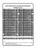
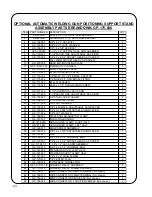
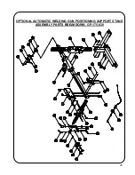
OPTIONAL AUTOMATIC WELDING GUN POSITIONING SUPPORT STAND 

ASSEMBLY PARTS BREAKDOWN, GP-175-030 

ITEM PART NUMBER DESCRIPTION

QTY

1

KR-2000-A

VERTICAL 1-1/2" RACK ARM BRACKET

1

2

KR-2000-B

HORIZONTAL 1-1/2" RACK ARM BRACKET

1

3

GK-108-065

3/8"-16 x 1" HEX BOLT

2

4

GK-136-063

3/8" SPLIT LOCK WASHER

2

5

GK-108-076

3/8"-16 x 5/8" HEX BOLT

2

6

GPS-150-007

1-1/2" x 36" SPECIAL RACK ARM ASSEMBLY

1

7

GK-190-655

1-1/2" MICRO FINE ADJUSTABLE RACK BOX

2

8

GK-107-086

1/4"-20 x 2-3/4" SOCKET HEAD CAP SCREW

2

9

M6 x 20MM SOCKET HEAD CAP SCREW

2

10

GS-472-005

RACK BOX MOUNTING PLATE

1

11

GP-175-031-100 PNEUMATIC CYLINDER

1

12

GP-175-033

FLOW CONTROL VALVE

2

13

GP-175-032

24 VAC SOLENOID VALVE

1

14

GP-175-036

1/8" MALE TO 1/4" FEMALE ADAPTOR

1

15

GP-175-034

1/4" QUICK FIT, UNIVERSAL FITTING

2

16

GK-111-069

#4 FLAT WASHER

2

17

GK-112-098

#4-40 x 1-1/4" ROUND HEAD SCREW

2

18

4

19

GS-472-006

1-1/2" HORIZONTAL RACK ARM

1

20

GK-171-655

1-1/8" MICRO FINE ADJUSTABLE RACK BOX

1

21

GK-129-007

3/8" STAR LOCK WASHER

3

22

GK-166-183

1-1/8" SWIVEL CLAMP

2

23

GK-111-058

3/8" FLAT WASHER

3

24

GK-153-004

3/8"-16 FEMALE, ADJUSTABLE HAND LEVER

2

25

GK-153-002

1/4"-20 x 0.984" ADJUSTABLE HAND LEVER

1

26

GK-111-066

1/4" FLAT WASHER

1

27

GK-186-003

RIGHT ANGLED ADAPTOR CLAMP

1

28

GK-187-027

INSULATOR BUSHING

1

29

GK-187-026R

GUN HOLDER CLAMP, RIGHT HALF

1

30

GK-187-026L

GUN HOLDER CLAMP, LEFT HALF

1

31

GK-190-077

KNOB SCREW ASSEMBLY

2

32

GK-153-005

3/8"-16 x 1.575" ADJUSTABLE HAND LEVER

1

33

GK-187-051

LINK

1

34

GK-160-006

3/8"-16 x 2-1/2" CARRIAGE BOLT

1

35

GK-107-067

1/4"-20 x 2-1/4" SOCKET HEAD CAP SCREW

2

36

GK-171-047-1

1-1/8" x 12" RACK ARM ASSEMBLY

1

37

GK-160-010

3/8"-16 x 2-1/4" CARRIAGE BOLT

1

38

GK-181-032

STANDARD LONG CLAMP HALF

1

39

GK-181-031

STANDARD SHORT CLAMP HALF

1

40

GK-161-001

1/4"-20 x 2" WING SCREW

2

41

GP-175-035

1/8" VENTED PLUG

2

42

GK-150-089

3 PIN CABLE CONNECTOR

1

43

GK-191-P-071-B AUXILIARY RELAY ASSEMBLY

1

44

GP-175-026

AUXILIARY RELAY WIRING HARNESS

1

45

GK-156-017

WIRE CONNECTOR CRIMP TERMINAL (Not shown)

3

46

GK-156-019

WIRE CONNECTOR CRIMP TERMINAL (Not shown)

2

47

GK-156-042

WIRE CONNECTOR PIGGYBACK (Not shown)

2

48

GP-156-064

WIRE CONNECTOR, 2 POSITION FEMALE (Not shown)

1

Summary of Contents for GP-175-006

Page 1: ...05 953 4140 Fax 905 953 4138 e mail sales gullco com GULLCO INTERNATIONAL INC U S A Phone 440 439 8333 Fax 440 439 3634 e mail kat apk net GULLCO INTERNATIONAL U K LIMITED EUROPE Phone 44 1257 253579 Fax 44 1257 254629 e mail sales gullco co uk GULLCO INTERNATIONAL PTY LIMITED AUSTRALIA Phone 61 0 7 5496 9555 Fax 61 0 7 5496 9522 e mail katoz ozemail com au GULLCO INTERNATIONAL LIMITED INDIA Phone...

Page 2: ......

Page 3: ...n in the following Electrical Shock Prevention Do not use this equipment in damp or wet locations Do not expose this equipment to rain Never carry this equipment by the cables or pull the cables to disconnect from the receptacle Keep all cables from heat oil and sharp edges Inspect all cables periodically and replace if damaged Inspect the secureness of all cables periodically and repair if loose ...

Page 4: ... before servicing IMPORTANT READ THIS BEFORE OPERATING THE WELDING POSITIONER Important information regarding safety and operation of the GSP motor control used in the Cantilevered Welding Positioner is contained in a supplemental manual attached at the end of this manual It is equally important to read understand and apply the information contained within the manual The manual GD 031 has a title ...

Page 5: ...TY 150 LBS 68 KG 300 LBS 136 KG GP 175 015 GPP 175 015 0 75 12 5000 RPM 150 INCH LBS 172 KG CM 2 ECCENTRICITY 75 LBS 34 KG 150 LBS 68 KG DISTANCE LOAD IN MM LBS KGS 3 76 150 68 6 152 97 44 9 229 72 33 12 305 57 26 Stand alone weight 70 Lbs 31 8 Kg Supply voltage Either 42 115 or 230 VAC single phase 50 60 Hz 200 watts Rotary table 12 305mm diameter machined aluminum table with six 6 radial slots 3...

Page 6: ...optional equipment can interface with such items as welding trigger signals pneumatic gun positioning slides manual activation footswitches and gas purge solenoids Safety is greatly enhanced by the use of Gullco s low voltage 24 V control and power supply system that is available in three line voltage inputs I e 42 115 and 230 VAC single phase 50 60 Hz or any unregulated 24 VDC power supply at 220...

Page 7: ...t be connected to the terminal that is allocated for Neutral The Brown or Black wire must be connected to the terminal that is allocated for Live EQUIPMENT FOR AUTOMATED WELDING AND CUTTING FUSE MANUFACTURED FREQUENCY SERIAL NO www gullco com SUPPLY WATTS PHASE MODEL V NRTL C R Hz GULLCO INTERNATIONAL INC CLEVELAND OHIO U S A TEL 440 439 8333 GULLCO INTERNATIONAL PTY LIMITED KARIONG NSW AUSTRALIA ...

Page 8: ...re usually connected to the trigger signal connectors of the wire feeder or welding power source MECHANICAL INSTALLATION WARNING Check to ensure that no parts have become loose during transportation Bolt the cantilevered welding positioner to a fixed table using four 4 3 8 or 10mm bolts not supplied The center distances of these boltholes are 9 3 4 247 65mm wide by 19 482 6mm long Check that the g...

Page 9: ...power before reapplying the power to the motor control The fuse holder allows accessibility to the main fuse by pushing the cap in towards the main body and twisting in a counterclockwise direction The direction selection switch allows the operator to set the manual direction of rotation This is a three 3 position switch with the center position being Neutral no direction chosen WARNING Avoid chan...

Page 10: ... when installed the turntable will rotate in the direction and speed set by the Forward Neutral Reverse switch and the Speed Adjustment knob Rotation will cease if the Run Stop switch is placed in the Stop position the Forward Neutral Reverse switch is placed in the Neutral position the speed is set to zero or the optional footswitch is released when installed The optional remote foot switch GP 17...

Page 11: ...rameter is set to On stitch weld the cycle will continue as described in section 1 5 1 5 The weld rotation will stop when the angular rotation reaches the initial value set in the programmable Stitch Weld Angle P 7 parameter or every time it reaches the sum of the initial Stitch Weld Angle P 7 value plus the accumulative sums of each Stitch Weld Angle P 7 and No Weld Angle P 8 The programmable Cra...

Page 12: ...f the Crater Fill Slope Out Delay P 4 the optional arc signal relay will de energize and the programmable Post Weld Delay P 5 timing cycle will commence This allows time for any burn back and or post flow functions prior to the retraction of the optional pneumatic gun positioning slide where applicable 1 14 Upon completion of the Post Weld Delay the optional gun slide solenoid relay will be de ene...

Page 13: ...e to a complete stop prior to starting the next weld 2 8 1 Example the Stitch Weld Angle parameter is set to 20º and the No Weld Angle is set to 40º The no weld rotation would stop at 60º 120º 180º 240º etc 2 9 Upon completion of the fixed delay the optional arc signal relay will be re energized and the programmable Rotation Start Delay P 2 timing cycle will commence again This provides time for a...

Page 14: ...ront face which covers the recessed Program Variable Selector switch where applicable With the power turned on and the Run Stop switch in the Stop position rotate the Program Variable Selector switch to the variable parameter to be altered the Preset Cycle L E D will flash on and off The number of the variable parameter will be displayed when the Forward Neutral Reverse switch is in the Neutral po...

Page 15: ...crater fill function When the programmable Weld Cessation P 9 variable is set to 2 the Crater Fill Slope Out Delay is used to keep the turntable rotating for a programmable duration after the arc signal has been de activated providing a slope out function The variable value range is from 00 0 to 09 9 seconds in increments of 00 1 seconds P 5 Post Weld Delay This sets a delay after each crater fill...

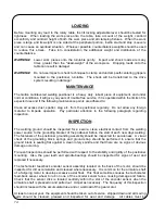
Page 16: ...ttention to the following paragraph regarding inspection INSPECTION The welding ground should be inspected for a secure clean electrical contact from the welding power source to the grounding bracket of the positioner before the start of each new days welding The fasteners of the positioner grounding assembly should be inspected for secureness A visual check of the grounding block springs and grou...

Page 17: ...ct or damage due to stacking of heavy objects on top of the equipment SHIPPING When shipping the Gullco cantilevered welding positioner the rotary table should be locked in the horizontal plane and the mounting table removed and safely packaged Packing should be placed in between the flat base and the cantilevered arm to offer support There should be sufficient room around the perimeter of the shi...

Page 18: ...it board assembly a 24 VAC pneumatic solenoid valve complete with control cable with mating quick connect plug a 4 101mm stroke pneumatic gun positioning slide a semi automatic adjustable gun clamp assembly a free standing bolt down support stand a 1 1 2 38 1mm micro fine rack box and rack arm assembly for vertical adjustment a 1 1 2 38 1mm micro fine rack box and rack arm assembly for horizontal ...

Page 19: ...tin number KR 1094 KR 2000 CSB Same as above except uses 1 1 2 38 1mm rack arms and rack boxes and provides 7 1 2 190 5mm of vertical and 6 1 2 165 1mm of horizontal adjustment Detailed information is provided in the Gullco sales bulletin number KR 1094 KR 1000 WSB A free standing support and welding gun holder assembly 1 1 8 28 6mm square rack arms and rack boxes provide 11 1 2 292 1mm of vertica...

Page 20: ...WITCH 1 25 GK 112 065 10 32 x 3 8 ROUND HEAD SCREW 4 74 GK 191 P 050 POWER ON OFF NAMEPLATE 1 26 GK 136 058 10 SPLIT LOCK WASHER 5 75 GP 150 040 BOTTOM COVER PLATE 1 27 GK 107 063 10 32 x 1 2 S H CAP SCREW 3 76 GK 112 089 8 32 x 1 4 ROUND HEAD SCREW 2 28 GK 160 003 1 2 13 x 2 CARRIAGE BOLT 1 77 GK 125 056 6 x 1 4 SELF TAPPING SCREW 1 29 GK 112 095 8 32 x 7 16 ROUND HEAD SCREW 4 78 GK 117 006 3 32 ...

Page 21: ...ILEVERED WELDING POSITIONER PARTS BREAKDOWN DRAWING GP 175 037 GPP 150 010 Gas Purge Adaptor Kit This kit replaces item numbers 7 8 9 and converts a regular GP positioner into a gas purge model GPP positioner ...

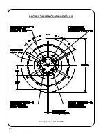
Page 22: ...20 Drawing Number GP 150 008 ROTARY TABLE MOUNTING DETAILS ...

Page 23: ...PACITORS 25 AMP 50 V PIV 350 SURGE MPS BRIDGE RECTIFIER 5A 42V OR 2 5A 115V OR 1 25A 230V SLOW BLOW FUSE 3 AMP 250V 42 115 OR 230V 200W STEP DOWN TRANSFORMER 10 000 µFD 35 WV CAPACITOR BROWN OR BLACK BLUE OR WHITE GREEN YELLOW OR GREEN BLACK RED 28 V FULL LOAD 35 V NO LOAD SUPPLY TO KAT CONTROL 910 Ohm 3 WATT DISCHARGE RESISTOR S P D T SWITCH ...

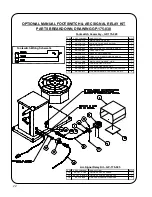
Page 24: ...112 CABLE STRAIN BRACKET 1 7 GK 112 084 10 32 x 1 4 ROUND HEAD SCREW 1 8 GK 148 014 STRAIN RELIEF 1 9 RM 111 105 FOOT SWITCH CABLE 10 6 1 10 GK 148 015 STRAIN RELIEF 7 8 O D 1 11 GK 148 017 STRAIN RELIEF LOCK NUT 1 12 GK 156 032 WIRE CONNECTOR 3 POSITION FEMALE 1 13 GK 156 017 WIRE CONNECTOR TERMINAL CRIMP 3 ITEM PARTNUMBER DESCRIPTION QTY 14 GK 191 P 104 AUXILIARY RELAY CABLE 1 15 GK 191 P 070 A ...

Page 25: ...WILL RESULT IN DAMAGE TO THE DRIVE SYSTEM ITEM PART NUMBER DESCRIPTION QTY 1 WPG 250 002 10 DIA GRIPPER BODY 1 2 WPG 250 003 GRIPPER JAWS SET OF 3 1 3 WPG 250 004 10 DIA GRIPPER SPIRAL SCROLL 1 4 GK 119 060 6 250 SHAFT DIA RETAINING RING 1 5 GK 107 074 5 16 18 x 1 1 4 SOCKET HEAD CAP SCREW 3 6 GK 107 106 M8 x 30mm SOCKET HEAD CAP SCREW NOT SHOWN 3 7 GBM 15 002 E 1 4 ALLEN KEY NOT SHOWN 1 ...

Page 26: ...HER 3 22 GK 166 183 1 1 8 SWIVEL CLAMP 2 23 GK 111 058 3 8 FLAT WASHER 3 24 GK 153 004 3 8 16 FEMALE ADJUSTABLE HAND LEVER 2 25 GK 153 002 1 4 20 x 0 984 ADJUSTABLE HAND LEVER 1 26 GK 111 066 1 4 FLAT WASHER 1 27 GK 186 003 RIGHT ANGLED ADAPTOR CLAMP 1 28 GK 187 027 INSULATOR BUSHING 1 29 GK 187 026R GUN HOLDER CLAMP RIGHT HALF 1 30 GK 187 026L GUN HOLDER CLAMP LEFT HALF 1 31 GK 190 077 KNOB SCREW...

Page 27: ...25 OPTIONAL AUTOMATIC WELDING GUN POSITIONING SUPPORT STAND ASSEMBLY PARTS BREAKDOWN GP 175 030 ...

Page 28: ...26 REVISIONS LIST September 2002 Overall First release ...

Page 29: ...DA Phone 905 953 4140 Fax 905 953 4138 e mail sales gullco com GULLCO INTERNATIONAL INC U S A Phone 440 439 8333 Fax 440 439 3634 e mail kat apk net GULLCO INTERNATIONAL U K LIMITED EUROPE Phone 44 1257 253579 Fax 44 1257 254629 e mail sales gullco co uk GULLCO INTERNATIONAL PTY LIMITED AUSTRALIA Phone 61 0 7 5496 9555 Fax 61 0 7 5496 9522 e mail katoz ozemail com au GULLCO INTERNATIONAL LIMITED I...

Page 30: ......

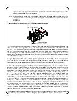
Page 31: ...faceplate and the Program Variable Selector Switch recessed below or extending through the faceplate and relevant hardware Gullco has a range of various product and application specific micro processor chips which can be used with any three variations of the GSP controls providing various degrees of functionality to the application GSP control Part Number Style of Cycle Push Button Style of Progra...

Page 32: ...e GSP control by either powering down the control or by placing the control in Hold stop mode to clear the error Er 4 As port CN302 is usually used to interface normally closed travel limit switches a closed circuit between pins 1 and 2 indicate a non activated reverse travel limit switch and a closed circuit between pins 1 and 4 indicate a non activated forward travel limit switch a third limit s...

Page 33: ...ing of tach feed back pulses used to measure distance travelled Open loop i e no tach feed back may be acceptable for manual motor operation in situations where the motor sensor is temporarily damaged the motor sensor is susceptible to failure due to an exceptionally harsh environment or where accurate calibrated speed is not required and the loading of the motor is constant Various input and outp...

Page 34: ...y of the program variable parameters where applicable RUN This removes the STOP command and allows the control to assume an operational status FORWARD When the switch is in this position the control will drive the motor in the Forward direction while in manual mode and when so permitted It is also used to select increment as the method of adjustment for the program variables Command Forward Motion...

Page 35: ... Cycle Push Button continually for one second while the control is in Hold Stop mode may the preset cycle routine be toggled form enabled to disabled as indicated by the non illumination of the Auto Cycle Mode L E D The Cycle Push Button is also used to increment decrement the values settings of the program variables where applicable The L E D Display The control has an L E D display that indicate...

Page 36: ...automatic cycle mode When the L E D is not illuminated the Preset Cycle is disabled manual mode A flashing Preset Cycle L E D indicates that either the Program Variables or the Motor Control Variables are being accessed either the Program Variable Selector Switch or the Motor Control Variable Rotary Switch is in a position other than zero 0 The motor control will not operate in this condition The ...

Page 37: ...ers are recessed and require the removal of a hole plug for access and a small flat bladed screwdriver for adjustment Zero 0 top dead center is the normal operating location for the switch When in any position other than zero 0 the control is in programming mode the round Preset Cycle L E D in the bottom right hand corner of the display will flash and the motor control will not allow normal operat...

Page 38: ...s are physically identical The dc supply to the control must remain connected to CN101 To make changes to the Motor Control Variables you must have access to the front and back of the control assembly Only when safe to do so turn on the power to the control With the power turned on and the Run Stop switch in the Stop position rotate the Motor Control Variable Rotary Switch to the variable paramete...

Page 39: ...entimetres per minute CEn or non specific rAd When the closed loop tach feedback is connected and if the inches per minute option is selected the IPM L E D will illuminate or if the centimetres per minute option is selected the CM MIN L E D will illuminate or if the non specific option is selected neither the IPM nor the CM MIN L E D s will illuminate P 7 Braking This sets the level of motor braki...

Page 40: ...igits even though the speed displayed is only three digits After the calibration process has been completed the three least significant digits are not displayed As mentioned earlier the accuracy of the calculated engineering unit output is only as good as the calibration of the control relevant to the actual speed The following example shows how to calculate the actual full speed of a Gullco KAT c...

Page 41: ...IMUM SPEED KAT CARRIAGES IMPERIAL METRIC GK 200 RL 16 3625 MIN 41 5607 CM MIN GK 200 RM 32 7249 MIN 83 1213 CM MIN GK 200 RH 88 3573 MIN 224 428 CM MIN GK 200 RL C W HI SPEED GEAR TRAIN 43 6332 MIN 110 828 CM MIN GK 200 RM C W HI SPEED GEAR TRAIN 87 2665 MIN 221 657 CM MIN GK 200 RH C W HI SPEED GEAR TRAIN 235 619 MIN 598 473 CM MIN GK 200 RL C W LOW SPEED GEAR TRAIN 6 98132 MIN 17 7325 CM MIN GK ...

Page 42: ...ontrol Connection Details Note CN101 CN201 are Molex 0 093 2 36mm series connectors CN101 Power Supply Input Pin 1 Optional earth ground Pin 2 common Pin 3 24 to 38 Vdc supply Note Pin 1 is not required when control faceplate is secured to a conductive earthed plane CN201 Motor Output Pin 1 Motor output Pin 2 Motor output Note CN101 F101 CN301 CN302 SW404 CN303A CN303B CN304B CN304A CN202 CN201 U4...

Page 43: ...ted to this port and will not look for the auxiliary Hold stop signal Therefore any auxiliary Hold stop device that is connected to the control after it has been powered up will be ignored After the microprocessor has recognised that a device is connected to this port it will activate the Hold stop command when pin 1 2 are in a closed circuit CN302 Limit Switch Monitoring Input Typical Pin 1 Commo...

Page 44: ...in 1 Common Pin 2 Spare not used Pin 3 Transistor collector out Pin 4 12 V Note Depending upon the product application specific micro processor chip installed this port in conjunction with one of Gullco s optional auxiliary relay modules may be used to activate such things as pneumatic solenoid valves safety circuits etc that may be part of the automatic cycle routine Pin 3 and Pin 4 are typically...

Page 45: ...191 P 235 ROTARY SPEED ENCODER 1 6 GK 191 P 236 CYCLE PUSH BUTTON EXTENDED 1 7 GSP 2007 FORWARD NEUTRAL REVERSE SWITCH 1 8 GSP 2011 PROGRAM VARIABLE SELECTOR SWITCH RECESSED 1 9 GSP 2008 RUN STOP SWITCH 1 10 GSP 2006 15 AMP FUSE 1 11 GK 191 P 097 SPEED SELECTOR KNOB 1 12 GK 151 004 GROMMET 1 13 GK 155 006 1 2 HOLE PLUG 1 14 GK 112 091 2 56 x 1 4 PAN HEAD SCREW 4 15 GSP 2004 X MICRO PROCESSOR CHIP ...

Page 46: ...1 P 235 ROTARY SPEED ENCODER 1 6 GSP 2009 CYCLE PUSH BUTTON RECESSED 1 7 GSP 2007 FORWARD NEUTRAL REVERSE SWITCH 1 8 GSP 2011 PROGRAM VARIABLE SELECTOR SWITCH RECESSED 1 9 GSP 2008 RUN STOP SWITCH 1 10 GSP 2006 15 AMP FUSE 1 11 GK 191 P 097 SPEED SELECTOR KNOB 1 12 GK 151 004 GROMMET 1 13 GK 155 003 1 2 PLASTIC HOLE PLUG 2 14 GK 112 091 2 56 x 1 4 PAN HEAD SCREW 4 15 GSP 2004 X MICRO PROCESSOR CHI...

Page 47: ...ENCODER 1 6 GK 191 P 236 CYCLE PUSH BUTTON EXTENDED 1 7 GSP 2007 FORWARD NEUTRAL REVERSE SWITCH 1 8 GSP 2012 PROGRAM VARIABLE SELECTOR SWITCH EXTENDED 1 9 GSP 2008 RUN STOP SWITCH 1 10 GSP 2006 15 AMP FUSE 1 11 GK 191 P 097 SPEED SELECTOR KNOB 1 12 GK 151 004 GROMMET 1 13 GK 194 O 023 SMALL SELECTOR KNOB 1 14 GK 112 091 2 56 x 1 4 PAN HEAD SCREW 4 15 GSP 2004 X MICRO PROCESSOR CHIP SPECIFY PROGRAM...

Page 48: ...T 18 GSP DRIVER BOARD SCHEMATIC GSP 2002 Drawing Revision E PCB Revision D ...

Page 49: ...T 19 GSP DISPLAY BOARD SCHEMATIC GSP 2003 Drawing number GK 191 224 ...

Page 50: ...2002 Title Page Updated Gullco Australia s phone fax numbers Page T 11 Changed Kat carriage part numbers in table from GK 191 P to GK 200 R series and from GK 192 F to GK 200 F series Page T 17 Added GK 151 005 selector knob grommet ...

Page 51: ...ggy Trackless Fillet Welding Travel Carriage The Gullco Moggy portable trackless fillet welding travel carriage system automates and adds accuracy and uniformity to welding cutting opera tions It is ideal for automatic horizon tal fillet lap and butt welding opera tions and can be equipped with controls for continuous and or stitch weld operations MODEL GM 01 050 Equipped with continuous travel co...

Reviews: