T-3
GENERAL SPECIFICATIONS
The GSP-2000, GSP-2001 and GSP-2010 microprocessor based motor controls are 24 vdc, full
“H”-Bridge, pulse width modulation controls with regenerative braking. They are designed to run 24
vdc motors and require a 24 to 38 vdc no-load supply (30 to 38 vdc is usually required for Gullco
products to meet specifications), usually derived form a full bridge rectified 22-24 vac source. The
required wattage of the supply depends upon the size of the motor. These controls can operate
any motor with a capacity of up to 250 Watts (1/3 horse power).
These controls can either operate with or without a closed loop tach feed back system attached to
the armature of the motor. A tach feed back is normally recommended as it allows the motor
control to constantly monitor and correct the speed of the motor providing accurate speed control
regardless of any variance in loading. A tach feed back system is also necessary when automatic
cycles are required, or when using engineering units (counting of tach feed back pulses, used to
measure distance travelled). Open loop (i.e. no tach feed back) may be acceptable for manual
motor operation in situations where; the motor sensor is temporarily damaged; the motor sensor is
susceptible to failure due to an exceptionally harsh environment; or where accurate calibrated
speed is not required and the loading of the motor is constant.
Various input and output ports are provided which are either optically coupled or transistor outputs.
These ports are described in detail later in this manual.
An L.E.D. display is provided to indicate the status of the control. This display is described in detail
later in this manual.
A varied selection of programmed micro-processor chips allow the controls to behave in specific
ways that are suited with the motorized equipment and process that the controls are being applied
to. Typically, each micro-processor chip allows full manual operation of the motor and usually
provides; automatic cycle routines; programming ability for the operator to set and fine tune the
automatic cycles to that desired; and external interfacing. Refer to the manual for the specific
product/micro-processor chip for details.
GENERAL DIMENSIONS
Summary of Contents for GP-175-006
Page 2: ......
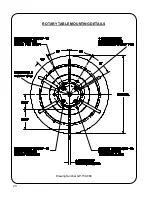
Page 22: ...20 Drawing Number GP 150 008 ROTARY TABLE MOUNTING DETAILS ...
Page 28: ...26 REVISIONS LIST September 2002 Overall First release ...
Page 30: ......
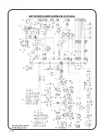
Page 48: ...T 18 GSP DRIVER BOARD SCHEMATIC GSP 2002 Drawing Revision E PCB Revision D ...
Page 49: ...T 19 GSP DISPLAY BOARD SCHEMATIC GSP 2003 Drawing number GK 191 224 ...


