T-7
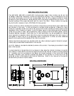
the direction selected at the speed set by the Variable Speed Control Knob. The speed may be
adjusted at any time and the manual motion may be stopped by placing either the Run/Stop switch
in the Stop position or by placing the Forward/Neutral/Reverse switch in the Neutral position.
AUTOMATIC MODE - To place the control in automatic mode (enable the preset cycle), with the
power on, place the Run/Stop switch in the Stop position. Then continually press the Cycle Push
Button until the display shows “Aut” (the Preset Cycle L.E.D. will be illuminated). While the control
is in automatic mode, the automatic cycle is usually initiated by placing the
Forward/Neutral/Reverse switch in the desired travel direction (if applicable), and placing the
Run/Stop switch in the Run position. When the automatic cycle has completed, the display will
show “End” and the “Hold” (stop) L.E.D. will flash, indicating the need to reset the Autocycle by
placing the Run/Stop switch in the Stop position before another automatic cycle may be initiated.
The automatic cycle may be aborted at any time by placing the Run/Stop switch in the Stop
position. The welding/cutting speed may usually be adjusted at any time during an automatic cycle.
PROGRAM VARIABLE ADJUSTMENTS
Program Variables are adjustable parameters available to the operator that determine the
functionality, and allow fine-tuning, of the automatic cycle operation.
Note:- Not all GSP
product/application specific micro-processor chips provide program variables - refer to the
manual for the specific machine or specific micro-processor chip for further details.
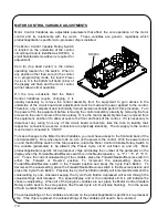
The Program Variable Selector switch is located between and below the Run/Stop and the
Forward/Neutral/Reverse switches. Some GSP controls are equipped with extended Program
Variable Selector switches, which come through the faceplate of the control. Others are recessed
and require the removal of a hole-plug for access and a small flat-bladed screwdriver for
adjustment.
Zero (0) (top dead center) is the normal operating location for the switch. When in any position
other than zero (0) the control is in programming mode, the round,
Preset Cycle L.E.D.
in the bottom
right hand corner of the display will flash and the motor control will not allow normal operation.
To make changes to the program variables (where available), remove the hole plug on the front
face which covers the recessed Program Variable Selector switch (where applicable). With the
power turned on and the Run/Stop switch in the Stop position, rotate the Program Variable Selector
switch to the variable (parameter) to be altered (the Preset Cycle L.E.D. will flash on and off). Most
product/application specific micro-processor chips will display the number of the parameter on the
display when the Forward/Neutral/Reverse switch is in the Neutral position. I.e. “P. 1”, “P. 2”, “P. 3”,
etc. To see the current value/setting of the variable, place the Forward/Neutral/Reverse switch in
either the Forward or Reverse position. To increment the value/setting, place the
Forward/Neutral/Reverse switch in the Forward position and press the Cycle Push Button. To
decrement the value/setting, place the Forward/Neutral/Reverse switch in the Reverse position and
press the Cycle Push Button. Pressing the Cycle Push Button briefly will increment/decrement the
value/setting by one, whereas keeping the Cycle Push Button depressed will scroll through the
values/settings until released. The speed display and or the individual L.E.D.’s will indicate the
chosen value/setting. When all of the program variables are set, place the Program Variable
Selector switch back to the zero position (the Preset Cycle L.E.D. will stop flashing) and re-insert
the hole-plug (where applicable).
The values/settings of the variables are stored on the product/application specific micro-processor
chip. If the chip is replaced, the values/settings of the variables will need to be re-entered.
Summary of Contents for GP-175-006
Page 2: ......
Page 22: ...20 Drawing Number GP 150 008 ROTARY TABLE MOUNTING DETAILS ...
Page 28: ...26 REVISIONS LIST September 2002 Overall First release ...
Page 30: ......
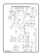
Page 48: ...T 18 GSP DRIVER BOARD SCHEMATIC GSP 2002 Drawing Revision E PCB Revision D ...
Page 49: ...T 19 GSP DISPLAY BOARD SCHEMATIC GSP 2003 Drawing number GK 191 224 ...


