7
OPERATION
Through the use of the optical tachometer closed loop feedback circuitry, the motor control can
obtain constant speed control of the cantilevered welding positioner, as well as determine the
amount of rotational distance travelled. The motor and the control operate on 24 VDC, supplied by
a power supply located in the base of the positioner tower. Therefore, all operator interface devices
(except the power on/off switch) are subjected to signal level voltages only.
The power On/Off switch is used to disconnect the power to the rest of the control circuitry.
I = on, O = off.
WARNING!
The motor control must not be continually started and stopped by the removal and
reapplying of power to the control. Turning the power off to the control will not
provide instant braking and continued use will damage the control. Allow ten (10)
seconds after the removal of power before reapplying the power to the motor control.
The fuse holder allows accessibility to the main fuse by pushing the cap in towards the main body
and twisting in a counterclockwise direction.
The direction selection switch allows the operator to set the manual direction of rotation. This is a
three (3) position switch with the center position being "Neutral" (no direction chosen).
WARNING!
Avoid changing the direction of rotation without making sure that rotation comes to a
complete stop first. Failure to comply may cause an overload.
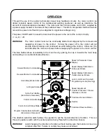
Command Forward Motion
Speed & Parameter Value
Display
Speed Display Calibrated in
Inches per Minute
Speed Display Calibrated in
Centimeters per Minute
Auto Cycle Mode (Constant)
Programming mode (Flashing)
Speed Adjustment
Counter-Clockwise = Slower
Clockwise = Faster
Neutral
Command Reverse Motion
Program Variable Selector Switch
(Extended or Recessed)
Control in Run Mode
Cycle Push Button
(Extended or Recessed)
Arc Signal Active
Hold (Stop) Mode Active
Reverse Motion Commanded
Forward Motion Commanded
Control in Hold (Stop) Mode
Summary of Contents for GP-175-006
Page 2: ......
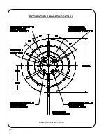
Page 22: ...20 Drawing Number GP 150 008 ROTARY TABLE MOUNTING DETAILS ...
Page 28: ...26 REVISIONS LIST September 2002 Overall First release ...
Page 30: ......
Page 48: ...T 18 GSP DRIVER BOARD SCHEMATIC GSP 2002 Drawing Revision E PCB Revision D ...
Page 49: ...T 19 GSP DISPLAY BOARD SCHEMATIC GSP 2003 Drawing number GK 191 224 ...


