13
.............................
CCEC/ OM Manual RotaSec Titan 1.5 EN
08.2009
Technical Details
An all welded steel rotor with straight arms runs in a phosphor bronze bearing at the top end and
supported by a ball and cone bearing at the base.
On double units models are available with interlocking rotors, where space is of prime importance.
Entry and Exit can be made by Card reader, Pushbutton or any other type of control device specified
by the client at the time of order.
All controls are housed within the unit, therefore NO separate switches or control boxes are required.
Control of the rotor is achieved usually by an electro-mechanism mounted within the top section of the
RotaSec and accessible by removing the Head Cover. Purely mechanical control is also possible.
On double units models are available with interlocking rotors, where space is of prime importance.
A positive action lock which prevents two passages at one time.
A self-centring mechanism to ensure complete rotation of the head to the reset position.
A hydraulic damper to ensure smooth and quiet operation.
An anti-backup device prevents reverse rotation when the head has moved 32° from
the rest position.
Standard Technical Specification
Orientation:
Pass left or Pass Right
Rotor Arms:
3N
O
for the RotaSec 120
4N
O
for the RotaSec 90
Drive:
Manually Operated
Materials:
Casework:
Square and circular hollow section mild steel, Hot
Zinc sprayed after manufacture. Painted to the
standard RAL colour range
Rotor Column:
Mild steel construction, Hot Zinc Sprayed, with a
with a white wet sprayed paint finish.
Function
:
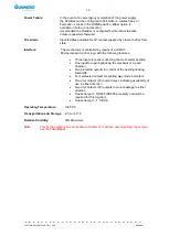
Passage in both directions, electronically controlled.
Mechanism
:
Control of the RotaSec operation is achieved by an electro-mechanical
head mechanism.
The Head has damping fitted as standard.
Security:
Passage through the “dead area” is prevented by stator bars.
Power Supply
:
115/230 Vac 50/60Hz
Power Rating
:
Standby or Passage 50Va (Alarm Condition 50Va)
Logic Voltage
:
24Vdc
Summary of Contents for RotaSec B120D
Page 2: ...CCEC OM Manuals RotaSec Titan 1 5 08 2009...
Page 11: ...11 CCEC OM Manual RotaSec Titan 1 5 EN 08 2009 Typical Units Model B90S Model F90S...
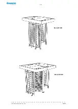
Page 12: ...12 CCEC OM Manual RotaSec Titan 1 5 EN 08 2009 Model R120S Model R120DI...
Page 61: ...61 CCEC OM Manual RotaSec Titan 1 5 EN 08 2009...
Page 63: ...63 CCEC OM Manual RotaSec Titan 1 5 EN 08 2009 Model S90S Model R90S...
Page 64: ...64 CCEC OM Manual RotaSec Titan 1 5 EN 08 2009 Model R120S Model S120S...
Page 65: ...65 CCEC OM Manual RotaSec Titan 1 5 EN 08 2009 Model F90D...
Page 66: ...66 CCEC OM Manual RotaSec Titan 1 5 EN 08 2009 Model F120D...
Page 67: ...67 CCEC OM Manual RotaSec Titan 1 5 EN 08 2009 Model R90D...
Page 68: ...68 CCEC OM Manual RotaSec Titan 1 5 EN 08 2009 Model R120D...
Page 69: ...69 CCEC OM Manual RotaSec Titan 1 5 EN 08 2009 Model S90D...
Page 70: ...70 CCEC OM Manual RotaSec Titan 1 5 EN 08 2009 Model S120D...
Page 71: ...71 CCEC OM Manual RotaSec Titan 1 5 EN 08 2009 Model F90DI...
Page 72: ...72 CCEC OM Manual RotaSec Titan 1 5 EN 08 2009 Model F120DI...
Page 73: ...73 CCEC OM Manual RotaSec Titan 1 5 EN 08 2009 Model R90DI...
Page 74: ...74 CCEC OM Manual RotaSec Titan 1 5 EN 08 2009 Model R120D...
Page 75: ...75 CCEC OM Manual RotaSec Titan 1 5 EN 08 2009 Model S90DI...
Page 76: ...76 CCEC OM Manual RotaSec Titan 1 5 EN 08 2009 Model S120DI...
Page 84: ...84 CCEC OM Manual RotaSec Titan 1 5 EN 08 2009 Fig 5 31 Optional Pushbuttons...
Page 98: ...98 CCEC Product Data CCEC O M Manuals ClearSec 1 3 09 2008 Notes...
Page 99: ...99 CCEC OM Manual RotaSec Titan 1 5 EN 08 2009 Notes...


