25
.............................
CCEC/ OM Manual RotaSec Titan 1.5 EN
08.2009
Damping Adjustment
An adjustable hydraulic damper is be fitted to the head assembly. This reduces the shock and noise
which can occur when the turnstile rotor reaches the home position.
Figure 4.10 - Hydraulic Damper
The damper should be adjusted to suit user preference and the weight diameter of the rotor.
Note -
There is some interaction between the damper setting and restoring force.
First set the damping as required for the application by unlocking the grub screw, swinging the rotor as
hard as possible, adjusting the damper by means of the rotor adjustment on the side of the damper, so
that the rotor comes to a controlled stop at the home position. Zero is minimum damping, 6 maximum.
Final adjustment is fairly critical and sensitive.
The restoring force can then be adjusted as in the previous section, so that the rotor will return to the
home position against the resistance of the damping. Check this by rotating the unit until the Cam
contacts the damper roller with the head stationary. A properly adjusted restoring mechanism should
then always return the unit to the home position.
Note -
It may be necessary to increase the restoring force then it may be necessary to further increase
the damping slightly and therefore a little more restoring force may then also be required.
It is a question of balancing the one against the other, making adjustment as necessary until the
system is tuned.
Electrical Connections
The locking solenoids have flying loom with shrouded male connectors. Polarity of the connection to
the solenoids is unimportant.
It is recommended that the head unit is connected to Earth. A M5 threaded stud is provided for this
purpose.
Summary of Contents for RotaSec B120D
Page 2: ...CCEC OM Manuals RotaSec Titan 1 5 08 2009...
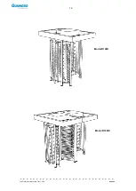
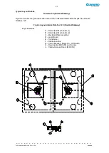
Page 11: ...11 CCEC OM Manual RotaSec Titan 1 5 EN 08 2009 Typical Units Model B90S Model F90S...
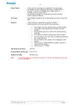
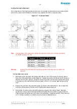
Page 12: ...12 CCEC OM Manual RotaSec Titan 1 5 EN 08 2009 Model R120S Model R120DI...
Page 61: ...61 CCEC OM Manual RotaSec Titan 1 5 EN 08 2009...
Page 63: ...63 CCEC OM Manual RotaSec Titan 1 5 EN 08 2009 Model S90S Model R90S...
Page 64: ...64 CCEC OM Manual RotaSec Titan 1 5 EN 08 2009 Model R120S Model S120S...
Page 65: ...65 CCEC OM Manual RotaSec Titan 1 5 EN 08 2009 Model F90D...
Page 66: ...66 CCEC OM Manual RotaSec Titan 1 5 EN 08 2009 Model F120D...
Page 67: ...67 CCEC OM Manual RotaSec Titan 1 5 EN 08 2009 Model R90D...
Page 68: ...68 CCEC OM Manual RotaSec Titan 1 5 EN 08 2009 Model R120D...
Page 69: ...69 CCEC OM Manual RotaSec Titan 1 5 EN 08 2009 Model S90D...
Page 70: ...70 CCEC OM Manual RotaSec Titan 1 5 EN 08 2009 Model S120D...
Page 71: ...71 CCEC OM Manual RotaSec Titan 1 5 EN 08 2009 Model F90DI...
Page 72: ...72 CCEC OM Manual RotaSec Titan 1 5 EN 08 2009 Model F120DI...
Page 73: ...73 CCEC OM Manual RotaSec Titan 1 5 EN 08 2009 Model R90DI...
Page 74: ...74 CCEC OM Manual RotaSec Titan 1 5 EN 08 2009 Model R120D...
Page 75: ...75 CCEC OM Manual RotaSec Titan 1 5 EN 08 2009 Model S90DI...
Page 76: ...76 CCEC OM Manual RotaSec Titan 1 5 EN 08 2009 Model S120DI...
Page 84: ...84 CCEC OM Manual RotaSec Titan 1 5 EN 08 2009 Fig 5 31 Optional Pushbuttons...
Page 98: ...98 CCEC Product Data CCEC O M Manuals ClearSec 1 3 09 2008 Notes...
Page 99: ...99 CCEC OM Manual RotaSec Titan 1 5 EN 08 2009 Notes...


