26
.............................
CCEC/ OM Manual RotaSec Titan 1.5 EN
08.2009
Sensor Timing and Solenoid Operation
The LCM02 microprocessor controller operates with a dc supply from the in-built PSU from 5 to 24v,
providing a negative going signal, when a sensor is active.
When a sensor is inactive the output V01, V02 or V03 will be high (at supply voltage) and the
corresponding indicating LED will illuminate. On activation the sensor output will drop to 0v and the
indicator LED will extinguish.
For the optimum operation it is recommended that when configured in fail safe mode (i.e. de-energised
to release) the solenoids are re-energised at the second sensor signal, i.e. sensor S2, output V02, for
pass left clockwise rotation or sensor S1, output V01, for pass right anti-clockwise rotation of the rotor.
When configured fail lock (i.e. energise to release) ideally the solenoids should be de-energised (to
lock) at the first sensor signal, i.e. sensor S1 output V01, for pass left clockwise rotation or sensor S2
output V02 for pass right anti-clockwise rotation of the rotor. This allows time for the solenoid
magnetic field to decay sufficiently to let the locking pawl drop before the rotor reaches the home
position.
Anti-reverse Ratchet Quietening Adjustment
The TITAN head quietening mechanism will have been tested and adjusted for correct operation.
However, during the life of the unit there may be some wear in the components.
Should adjustment be required, (indicated by ratchet noise as the head is rotated) the slotted grub
screws can be rotated clockwise with a screwdriver, quarter of a turn at a time until the ratchet noise is
eliminated.
Summary of Contents for RotaSec B120D
Page 2: ...CCEC OM Manuals RotaSec Titan 1 5 08 2009...
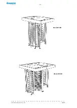
Page 11: ...11 CCEC OM Manual RotaSec Titan 1 5 EN 08 2009 Typical Units Model B90S Model F90S...
Page 12: ...12 CCEC OM Manual RotaSec Titan 1 5 EN 08 2009 Model R120S Model R120DI...
Page 61: ...61 CCEC OM Manual RotaSec Titan 1 5 EN 08 2009...
Page 63: ...63 CCEC OM Manual RotaSec Titan 1 5 EN 08 2009 Model S90S Model R90S...
Page 64: ...64 CCEC OM Manual RotaSec Titan 1 5 EN 08 2009 Model R120S Model S120S...
Page 65: ...65 CCEC OM Manual RotaSec Titan 1 5 EN 08 2009 Model F90D...
Page 66: ...66 CCEC OM Manual RotaSec Titan 1 5 EN 08 2009 Model F120D...
Page 67: ...67 CCEC OM Manual RotaSec Titan 1 5 EN 08 2009 Model R90D...
Page 68: ...68 CCEC OM Manual RotaSec Titan 1 5 EN 08 2009 Model R120D...
Page 69: ...69 CCEC OM Manual RotaSec Titan 1 5 EN 08 2009 Model S90D...
Page 70: ...70 CCEC OM Manual RotaSec Titan 1 5 EN 08 2009 Model S120D...
Page 71: ...71 CCEC OM Manual RotaSec Titan 1 5 EN 08 2009 Model F90DI...
Page 72: ...72 CCEC OM Manual RotaSec Titan 1 5 EN 08 2009 Model F120DI...
Page 73: ...73 CCEC OM Manual RotaSec Titan 1 5 EN 08 2009 Model R90DI...
Page 74: ...74 CCEC OM Manual RotaSec Titan 1 5 EN 08 2009 Model R120D...
Page 75: ...75 CCEC OM Manual RotaSec Titan 1 5 EN 08 2009 Model S90DI...
Page 76: ...76 CCEC OM Manual RotaSec Titan 1 5 EN 08 2009 Model S120DI...
Page 84: ...84 CCEC OM Manual RotaSec Titan 1 5 EN 08 2009 Fig 5 31 Optional Pushbuttons...
Page 98: ...98 CCEC Product Data CCEC O M Manuals ClearSec 1 3 09 2008 Notes...
Page 99: ...99 CCEC OM Manual RotaSec Titan 1 5 EN 08 2009 Notes...

