33
.............................
CCEC/ OM Manual RotaSec Titan 1.5 EN
08.2009
Voltage Free Outputs
The four relays K1, K2, K3 and K4 control an equal number of voltage free contacts that interface the
control logic with external components. The maximum capacity of the contacts is 0.5A max/30V.
Note
- The output contacts may be configured individually for normally open (NO) or normally
closed (NC) operation by suitably positioning the jumpers JP05, JP07, JP10 and JP12.
The logical function of the four outputs is dependent on the values set for certain programmable
parameters, Refer to the OPERATING SECTION of this manual.
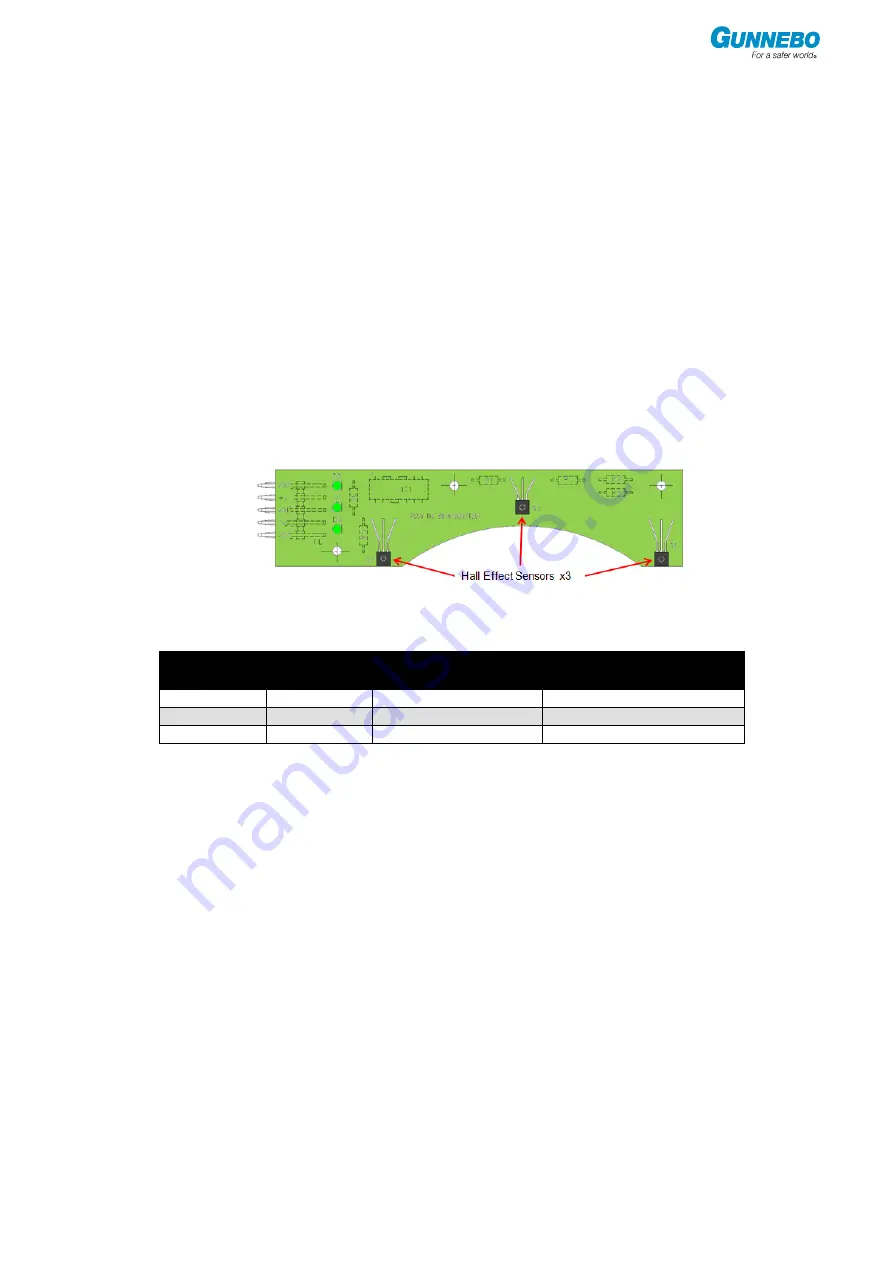
Sensor Board
The board provides an interface between the Titan mechanism and the LCM02 Controller Logic.
Mounted on it are the position sensors for the rotary unit and all the connections required to
operate the solenoids.
The sensor PCB assembly is fitted with a 5 way male connector.
Communication with the LCM02 PCB is made by means of a cable to the Board. This cable carries
+24Vdc for the Board supply, sensor signals and the commands for all solenoids.
Fig 4.14 - Sensor Board
LEDs
The board has 3 status LED‟s that indicate the operating status of the mechanism.
LED
Colour
Function
Description
DL1
Green
Status of Hall sensor 1
On when sensor engaged
DL2
Green
Status of Hall sensor 2
On when sensor engaged
DL3
Green
Status of Hall sensor 3
On when sensor engaged
Summary of Contents for RotaSec B120D
Page 2: ...CCEC OM Manuals RotaSec Titan 1 5 08 2009...
Page 11: ...11 CCEC OM Manual RotaSec Titan 1 5 EN 08 2009 Typical Units Model B90S Model F90S...
Page 12: ...12 CCEC OM Manual RotaSec Titan 1 5 EN 08 2009 Model R120S Model R120DI...
Page 61: ...61 CCEC OM Manual RotaSec Titan 1 5 EN 08 2009...
Page 63: ...63 CCEC OM Manual RotaSec Titan 1 5 EN 08 2009 Model S90S Model R90S...
Page 64: ...64 CCEC OM Manual RotaSec Titan 1 5 EN 08 2009 Model R120S Model S120S...
Page 65: ...65 CCEC OM Manual RotaSec Titan 1 5 EN 08 2009 Model F90D...
Page 66: ...66 CCEC OM Manual RotaSec Titan 1 5 EN 08 2009 Model F120D...
Page 67: ...67 CCEC OM Manual RotaSec Titan 1 5 EN 08 2009 Model R90D...
Page 68: ...68 CCEC OM Manual RotaSec Titan 1 5 EN 08 2009 Model R120D...
Page 69: ...69 CCEC OM Manual RotaSec Titan 1 5 EN 08 2009 Model S90D...
Page 70: ...70 CCEC OM Manual RotaSec Titan 1 5 EN 08 2009 Model S120D...
Page 71: ...71 CCEC OM Manual RotaSec Titan 1 5 EN 08 2009 Model F90DI...
Page 72: ...72 CCEC OM Manual RotaSec Titan 1 5 EN 08 2009 Model F120DI...
Page 73: ...73 CCEC OM Manual RotaSec Titan 1 5 EN 08 2009 Model R90DI...
Page 74: ...74 CCEC OM Manual RotaSec Titan 1 5 EN 08 2009 Model R120D...
Page 75: ...75 CCEC OM Manual RotaSec Titan 1 5 EN 08 2009 Model S90DI...
Page 76: ...76 CCEC OM Manual RotaSec Titan 1 5 EN 08 2009 Model S120DI...
Page 84: ...84 CCEC OM Manual RotaSec Titan 1 5 EN 08 2009 Fig 5 31 Optional Pushbuttons...
Page 98: ...98 CCEC Product Data CCEC O M Manuals ClearSec 1 3 09 2008 Notes...
Page 99: ...99 CCEC OM Manual RotaSec Titan 1 5 EN 08 2009 Notes...


