37
.............................
CCEC/ OM Manual RotaSec Titan 1.5 EN
08.2009
Section 5
Installation
Installation
Unpacking
On receipt of equipment on site, check all items are complete and undamaged. If for any reason
transit damage has occurred, ensure the extent of any damage is recorded and if considered
necessary report the incident to Gunnebo.
RotaSec models are delivered as partly assembled kit of parts, which may require lifting equipment
with working capacity of at least 600Kgs for off-loading and installation.
Retain all major component packaging for re-use in the event that items may need to be returned for
servicing during their life.
Tools Required
Step Ladder
One Metre Long (minimum) Spirit Level
Tape Measure
Set of Metric Allen Keys
Set of Metric Spanners
Hammer Drill
Chisel Attachment
Safety Gloves
Special Key Spanner (for access panel)
Diamond Drill bits for 12mm bolts
Tungsten Drill bits for 12mm bolts
Extension Lead
Generator (if power is not available)
Chalk Plum Line
Shims
Tool Kit - General
Safety Glasses
PLEASE READ ALL SECTIONS CAREFULLY BEFORE COMMENCING INSTALLATION
Site Preparation
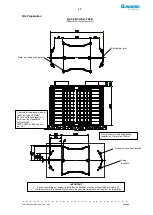
Ensure the site base area has been completed in accordance with the approved site installation
drawing. Reference to the Installation Figures Refer to Figs 5.1 to 5.20.should be made.
NOTES:
1. A concrete base suitable for external or internal use is required. Alternative types of base may be
acceptable subject to discussion with Gunnebo technical personnel.
2. Fixing centres, it is not necessary to pre-drill the base to receive the RotaSec, drilling is carried out
when the equipment is erected.
3. Conduit entry positions to suit the installations.
NOTE:
Items 1 and 3 are the responsibility of the client.
4. Should the base include a steel reinforcing mesh or be of hollow -pot or planked construction will
be encountered at less than 100mm below the finished floor level (FFL), Gunnebo technical
personnel must be consulted to agree a suitable method of securing the RotaSec.
NEVER
position the RotaSec to span an expansion joint in the base.
Site Preparation
Fig 5.1 RotaSec B90S
(Shown with straight bar rotor)
IMPORTANT
Any horizontal pipe or conduit runs below the RotaSec must be at least 140mm below FFL.
It is the
customer‟s responsibility to ensure the structural integrity and strength of the installation
location.
Straight bar rotor
Summary of Contents for RotaSec B120D
Page 2: ...CCEC OM Manuals RotaSec Titan 1 5 08 2009...
Page 11: ...11 CCEC OM Manual RotaSec Titan 1 5 EN 08 2009 Typical Units Model B90S Model F90S...
Page 12: ...12 CCEC OM Manual RotaSec Titan 1 5 EN 08 2009 Model R120S Model R120DI...
Page 61: ...61 CCEC OM Manual RotaSec Titan 1 5 EN 08 2009...
Page 63: ...63 CCEC OM Manual RotaSec Titan 1 5 EN 08 2009 Model S90S Model R90S...
Page 64: ...64 CCEC OM Manual RotaSec Titan 1 5 EN 08 2009 Model R120S Model S120S...
Page 65: ...65 CCEC OM Manual RotaSec Titan 1 5 EN 08 2009 Model F90D...
Page 66: ...66 CCEC OM Manual RotaSec Titan 1 5 EN 08 2009 Model F120D...
Page 67: ...67 CCEC OM Manual RotaSec Titan 1 5 EN 08 2009 Model R90D...
Page 68: ...68 CCEC OM Manual RotaSec Titan 1 5 EN 08 2009 Model R120D...
Page 69: ...69 CCEC OM Manual RotaSec Titan 1 5 EN 08 2009 Model S90D...
Page 70: ...70 CCEC OM Manual RotaSec Titan 1 5 EN 08 2009 Model S120D...
Page 71: ...71 CCEC OM Manual RotaSec Titan 1 5 EN 08 2009 Model F90DI...
Page 72: ...72 CCEC OM Manual RotaSec Titan 1 5 EN 08 2009 Model F120DI...
Page 73: ...73 CCEC OM Manual RotaSec Titan 1 5 EN 08 2009 Model R90DI...
Page 74: ...74 CCEC OM Manual RotaSec Titan 1 5 EN 08 2009 Model R120D...
Page 75: ...75 CCEC OM Manual RotaSec Titan 1 5 EN 08 2009 Model S90DI...
Page 76: ...76 CCEC OM Manual RotaSec Titan 1 5 EN 08 2009 Model S120DI...
Page 84: ...84 CCEC OM Manual RotaSec Titan 1 5 EN 08 2009 Fig 5 31 Optional Pushbuttons...
Page 98: ...98 CCEC Product Data CCEC O M Manuals ClearSec 1 3 09 2008 Notes...
Page 99: ...99 CCEC OM Manual RotaSec Titan 1 5 EN 08 2009 Notes...


