57
.............................
CCEC/ OM Manual RotaSec Titan 1.5 EN
08.2009
Headroom
A minimum floor to ceiling height of 2600mm must be provided to allow sufficient headroom for
erection and subsequent maintenance operations. For security applications, when it is undesirable to
leave a gap above the RotaSec an overhead grille or barrier must be provided which is removable to
allow installation or maintenance. Such infill's should be retained from the secure side, to maximise
security.
Conduit Routing
Conduit carrying cables for Power and Control, enter the RotaSec from under floor. Two conduit are
required normally, one for the Power supply, the other for the Control or data signals.
Conduit Routing From Under floor
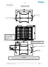
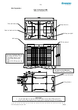
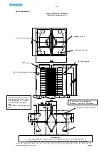
Conduit routed under floor must be sited accurately as shown on Site Preparations Diagram. Please
note that the standard locations indicated should be utilised where possible. We recommend the use
of 20mm diameter steel conduit which should be left protruding a minimum of 50mm above Finished
Floor Level to prevent the ingress of surface water.
Conduit Routing From Overhead
Gunnebo technical personnel MUST be advised at the time of order placement (or as soon as possible
thereafter) of this intention.
Cable Requirements
All conduits and cables MUST be provided by others. Cables must be laid in the
conduits and left with 4 metre long tails at the RotaSec position.
Power Cables
One conduit should be dedicated for the power supply from an external source and be run back to the
nearest fused spur. A triple-core, earthed 1.5mm
2
cable rated at a minimum of 10 amps should be
provided. The power supply cable must be isolated until installation has been completed and must be
terminated to a live supply by others. If Engineers from Gunnebo are erecting the unit, it is preferable
to arrange concurrent attendance of the site Electrical Contractors to position the conduits and
terminate cables.
RCCD (Earth Leakage Protection)
It is customer responsibility to ensure the incoming supply to the RotaSec meets current Regulations
and to fit appropriate safety devices accordingly.
Cable Controls
A second conduit should be provided, separate from that for the power supply, for any remote control
or data cabling requirements. Units controlled from simple remote switches, such as
pushbuttons/footswitches etc should be provided with either a four-core cable if bi-directional control is
specified, or twin-core if uni-directional
Such cables should be of minimum conductor size 0.5mm sq and laid in the conduit with a 4 metre tail
left at the RotaSec position. For these applications the control conduit should be routed back to the
control switch position and the cable left with a suitable tail for the switch.
For units controlled by a card access system or other equipment, the relevant manufacturer should be
consulted for any data-line or other cabling requirements for their equipment, whether or not the
controlling device is mounted directly to the RotaSec.
Summary of Contents for RotaSec B120D
Page 2: ...CCEC OM Manuals RotaSec Titan 1 5 08 2009...
Page 11: ...11 CCEC OM Manual RotaSec Titan 1 5 EN 08 2009 Typical Units Model B90S Model F90S...
Page 12: ...12 CCEC OM Manual RotaSec Titan 1 5 EN 08 2009 Model R120S Model R120DI...
Page 61: ...61 CCEC OM Manual RotaSec Titan 1 5 EN 08 2009...
Page 63: ...63 CCEC OM Manual RotaSec Titan 1 5 EN 08 2009 Model S90S Model R90S...
Page 64: ...64 CCEC OM Manual RotaSec Titan 1 5 EN 08 2009 Model R120S Model S120S...
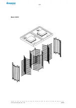
Page 65: ...65 CCEC OM Manual RotaSec Titan 1 5 EN 08 2009 Model F90D...
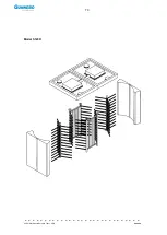
Page 66: ...66 CCEC OM Manual RotaSec Titan 1 5 EN 08 2009 Model F120D...
Page 67: ...67 CCEC OM Manual RotaSec Titan 1 5 EN 08 2009 Model R90D...
Page 68: ...68 CCEC OM Manual RotaSec Titan 1 5 EN 08 2009 Model R120D...
Page 69: ...69 CCEC OM Manual RotaSec Titan 1 5 EN 08 2009 Model S90D...
Page 70: ...70 CCEC OM Manual RotaSec Titan 1 5 EN 08 2009 Model S120D...
Page 71: ...71 CCEC OM Manual RotaSec Titan 1 5 EN 08 2009 Model F90DI...
Page 72: ...72 CCEC OM Manual RotaSec Titan 1 5 EN 08 2009 Model F120DI...
Page 73: ...73 CCEC OM Manual RotaSec Titan 1 5 EN 08 2009 Model R90DI...
Page 74: ...74 CCEC OM Manual RotaSec Titan 1 5 EN 08 2009 Model R120D...
Page 75: ...75 CCEC OM Manual RotaSec Titan 1 5 EN 08 2009 Model S90DI...
Page 76: ...76 CCEC OM Manual RotaSec Titan 1 5 EN 08 2009 Model S120DI...
Page 84: ...84 CCEC OM Manual RotaSec Titan 1 5 EN 08 2009 Fig 5 31 Optional Pushbuttons...
Page 98: ...98 CCEC Product Data CCEC O M Manuals ClearSec 1 3 09 2008 Notes...
Page 99: ...99 CCEC OM Manual RotaSec Titan 1 5 EN 08 2009 Notes...


