88
.............................
CCEC/ OM Manual RotaSec Titan 1.5 EN
08.2009
Components
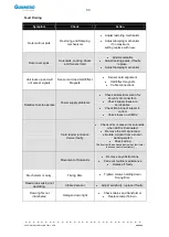
Annual Checks
(Operations to be carried out with the power supply and BBU disconnected)
Cables and Connectors
(Operations to be carried out with the power supply and BBU disconnected)
Check that the wire connectors are firmly attached.
Check that the terminals are fully tightened.
Check that the insulation of the wires is in good condition and that no conductors are exposed.
Check that mechanism fixings, screws and encoder grub screws are tight.
Carry out general testing as described previously.
Electrical Circuits
No general maintenance is required apart from replacement fuses in the event of a failure.
General Component Maintenance
Ensure the assembly is kept clean.
Replacing the LCM02
(Operations to be carried out with the power supply and BBU disconnected)
Note
- Before removing the PCB, record the position of the Jumpers and Connectors.
When replacing ensure the correct EPROM configuration is refitted.
Disconnect the power supplies.
Remove all connectors from the PCB .
If necessary remove the PCB supports and the small chip in Master side LCM02.
Disconnect the flat cable from the UCM95 (if the PCB is fitted)
Connect the Jumpers to the NEW PCB.
Insert the original EPROM from the old unit to the NEW PCB.
Reconnect the cables and connectors.
Replace the PCB.
Reconnect the power supplies.
Switch ON the Unit and return it to normal operation.
Replacing the Infrared Sensor
(Operations to be carried out with the power supply and BBU disconnected)
Disconnect the power supplies.
Remove the infrared sensor from the support bracket.
Remove all cables from the infrared sensor, taking note of their location.
Reconnect the cables.
Replace the infrared sensor onto the mounting bracket.
Reconnect the power supplies.
Switch ON the Unit and return it to normal operation.
Note
– Adjust the infrared sensitivity to suit as detailed in Section 5
Replacing Other Interface Cards
(Operations to be carried out with the power supply and BBU
disconnected)
Other Interface Cards may be fitted as specified at time of order.
Follow the same good practice procedures as detailed above.
Summary of Contents for RotaSec B120D
Page 2: ...CCEC OM Manuals RotaSec Titan 1 5 08 2009...
Page 11: ...11 CCEC OM Manual RotaSec Titan 1 5 EN 08 2009 Typical Units Model B90S Model F90S...
Page 12: ...12 CCEC OM Manual RotaSec Titan 1 5 EN 08 2009 Model R120S Model R120DI...
Page 61: ...61 CCEC OM Manual RotaSec Titan 1 5 EN 08 2009...
Page 63: ...63 CCEC OM Manual RotaSec Titan 1 5 EN 08 2009 Model S90S Model R90S...
Page 64: ...64 CCEC OM Manual RotaSec Titan 1 5 EN 08 2009 Model R120S Model S120S...
Page 65: ...65 CCEC OM Manual RotaSec Titan 1 5 EN 08 2009 Model F90D...
Page 66: ...66 CCEC OM Manual RotaSec Titan 1 5 EN 08 2009 Model F120D...
Page 67: ...67 CCEC OM Manual RotaSec Titan 1 5 EN 08 2009 Model R90D...
Page 68: ...68 CCEC OM Manual RotaSec Titan 1 5 EN 08 2009 Model R120D...
Page 69: ...69 CCEC OM Manual RotaSec Titan 1 5 EN 08 2009 Model S90D...
Page 70: ...70 CCEC OM Manual RotaSec Titan 1 5 EN 08 2009 Model S120D...
Page 71: ...71 CCEC OM Manual RotaSec Titan 1 5 EN 08 2009 Model F90DI...
Page 72: ...72 CCEC OM Manual RotaSec Titan 1 5 EN 08 2009 Model F120DI...
Page 73: ...73 CCEC OM Manual RotaSec Titan 1 5 EN 08 2009 Model R90DI...
Page 74: ...74 CCEC OM Manual RotaSec Titan 1 5 EN 08 2009 Model R120D...
Page 75: ...75 CCEC OM Manual RotaSec Titan 1 5 EN 08 2009 Model S90DI...
Page 76: ...76 CCEC OM Manual RotaSec Titan 1 5 EN 08 2009 Model S120DI...
Page 84: ...84 CCEC OM Manual RotaSec Titan 1 5 EN 08 2009 Fig 5 31 Optional Pushbuttons...
Page 98: ...98 CCEC Product Data CCEC O M Manuals ClearSec 1 3 09 2008 Notes...
Page 99: ...99 CCEC OM Manual RotaSec Titan 1 5 EN 08 2009 Notes...


