89
.............................
CCEC/ OM Manual RotaSec Titan 1.5 EN
08.2009
Down light
In the event that lamp replacement is necessary, remove the Down Light cover by unscrewing it and
lower the reflector assembly carefully. Remove and replace the lamp.
Note
- Care should be taken with lamp replacement to ensure that the fingers do not come in
contact with the glass of the lamp
Fault Finding
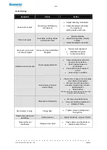
During normal operation of the mechanism, the control logic displays the status of certain signals.
This enables rapid testing of certain system functions.
Fig 6.1 - Logic Display
Display A
Display B
Segment
Display A
Display B
a
Status of sensor 2 of HC1/B board
b
Status of sensor 3 of HC1/B board
c
Input of reader permissive for
direction B
d
Up/Down encoder signal
e
Input of reader permissive for
direction A
f
Status of sensor 1 of HC1/B board
g
Encoder step signal
dp
When the rotor rotates, the segments (f )and (a) flash as they reproduce the signals from the Hall
sensors located near the upper cam of the rotary unit.
When the rotor is in the barrier position, segment b should be illuminated.
Segments d and g also flash, but these reproduce the signals generated by the internal logic of the
LCM02 board.
In the presence of a direction A permissive signal from the reader, segment e will illuminate. If the
permissive signal is for direction B, segment c will illuminate.
LCM02 Outputs Test
The control logic can operate in a test mode in which it is possible to operate the lock electromagnets
and switch on and off the LCM02 display.
Press and hold pressed pushbutton
SW3
Reset the microprocessor by pressing and releasing pushbutton
SW1
.
Release the pushbutton
SW3
.
At this point you can carry out the following tests.
Press
SW2
to energise the direction A lock electromagnet, relays K2 and K4 of the LCM02
board are energised, all display segments are off.
Press
SW3
to energise the direction B lock electromagnet, relays K1 and K3 of the LCM02
board are energised, all display segments on.
Press
SW4
to de-energise the electromagnets.
Note
- On completion of the test procedure you must press the reset button
SW1
to restore
normal operation of the control logic.
Summary of Contents for RotaSec B120D
Page 2: ...CCEC OM Manuals RotaSec Titan 1 5 08 2009...
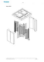
Page 11: ...11 CCEC OM Manual RotaSec Titan 1 5 EN 08 2009 Typical Units Model B90S Model F90S...
Page 12: ...12 CCEC OM Manual RotaSec Titan 1 5 EN 08 2009 Model R120S Model R120DI...
Page 61: ...61 CCEC OM Manual RotaSec Titan 1 5 EN 08 2009...
Page 63: ...63 CCEC OM Manual RotaSec Titan 1 5 EN 08 2009 Model S90S Model R90S...
Page 64: ...64 CCEC OM Manual RotaSec Titan 1 5 EN 08 2009 Model R120S Model S120S...
Page 65: ...65 CCEC OM Manual RotaSec Titan 1 5 EN 08 2009 Model F90D...
Page 66: ...66 CCEC OM Manual RotaSec Titan 1 5 EN 08 2009 Model F120D...
Page 67: ...67 CCEC OM Manual RotaSec Titan 1 5 EN 08 2009 Model R90D...
Page 68: ...68 CCEC OM Manual RotaSec Titan 1 5 EN 08 2009 Model R120D...
Page 69: ...69 CCEC OM Manual RotaSec Titan 1 5 EN 08 2009 Model S90D...
Page 70: ...70 CCEC OM Manual RotaSec Titan 1 5 EN 08 2009 Model S120D...
Page 71: ...71 CCEC OM Manual RotaSec Titan 1 5 EN 08 2009 Model F90DI...
Page 72: ...72 CCEC OM Manual RotaSec Titan 1 5 EN 08 2009 Model F120DI...
Page 73: ...73 CCEC OM Manual RotaSec Titan 1 5 EN 08 2009 Model R90DI...
Page 74: ...74 CCEC OM Manual RotaSec Titan 1 5 EN 08 2009 Model R120D...
Page 75: ...75 CCEC OM Manual RotaSec Titan 1 5 EN 08 2009 Model S90DI...
Page 76: ...76 CCEC OM Manual RotaSec Titan 1 5 EN 08 2009 Model S120DI...
Page 84: ...84 CCEC OM Manual RotaSec Titan 1 5 EN 08 2009 Fig 5 31 Optional Pushbuttons...
Page 98: ...98 CCEC Product Data CCEC O M Manuals ClearSec 1 3 09 2008 Notes...
Page 99: ...99 CCEC OM Manual RotaSec Titan 1 5 EN 08 2009 Notes...


