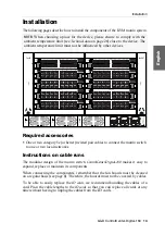
Installation
G&D ControlCenter-Digital-160 ·
15
English
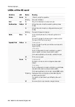
Connect the target computers to the different target modules.
Connect the
Transmission
interfaces of the individual target modules to one
Dynamic Port
of a compatible IO card..
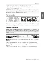
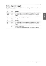
Power supply
Power ×:
Connect one of the supplied power cables for each installed power supply
module. Connect the power cable with a power socket and turn on the power switch.
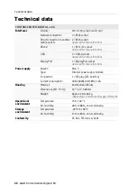
Network interfaces
Network A:
Plug in a category 5e (or better) twisted-pair cable, which is available as
accessory.
Connect the other end of the cable to a network interface of the local network.
Network B:
Plug in a category 5e (or better) twisted-pair cable, which is available as
accessory.
Connect the other end of the cable to a network interface of the local network.
IMPORTANT:
UC
variants of target modules provide two
Trans.
interfaces to con-
nect a computer to two
different
KVM matrix systems. Connect only one of the tar-
get module’s
Trans.
interfaces to this matrix switch!
NOTE:
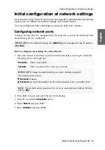
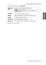
Connect the matrix switch to one or two local networks to configure it via
the
Config Panel
web application and to use the enhanced network functionalities
(for example authentication against directory services, time sync via NTP server,
netfilter or syslog).
PSU 3
AC
DC
Caution!
Use original parts only!
Read manual before installing!
Power 1
Power 2
Power 3
DisplayPort
USB
Network B
Network A
Status
Fail Ctrl
Ident.
Fail Comm.
Bus IN
Bus OUT
RS232
Service


