background image

Expanding switchable signals

22

 · G&D ControlCenter-Digital-160

Expanding switchable signals

You can expand a computer’s or a console’s switchable signals through 

channel 

grouping

.

The web application lets you assign up to seven additional video channels and one 

USB 2.0 or RS 232 channel to the KVM channel of the console.

You can assign up to seven additional video channels to the KVM channel of the com-

puter, too. In addition, you can create a 

pool

 of four devices for the USB 2.0/RS 232 

channel.

By using pools, you can grant up to four users the right to access the USB 2.0/

RS 232 channel 

at the same time

. For this, the matrix switch selects an available device 

from the pool after switching.

Assigning multiple channels to a console or computer creates a 

channel group

.

Detailed information on 

channel grouping

 can be retrieved in the web application 

manual.

EXAMPLE: 

To transmit a second video signal and a USB 2.0 signal of the same 

computer, in addition to the 

DVI-CPU

 computer module, connect a second 

DVI-CPU

module (second video channel) and a 

U2-CPU

 module (USB2.0/RS232) to the 

computer.
In addition to the 

DVI-CON

 user module, connect the 

DVI-CON-Video

 (second video 

channel) and a 

U2-CPU

 module (USB2.0/RS232) to the console, the aforemen-

tioned computer is accessing.

NOTE: 

Within the channel groups of the console a USB 2.0/RS 232 channel or a 

multi-channel represent one single device. For computers such a channel repre-

sents a group of up to four devices.

NOTE: 

The OSD does 

not 

show any user or computer modules that you added as 

additional channels to the channel group.

Summary of Contents for ControlCenter-Digital-160

Page 1: ...Guntermann Drunck GmbH www gdsys de ControlCenter Digital 160 A9100230 1 51 Installation und Bedienung DE EN Installation and Operation ...

Page 2: ...usschluss G D übernimmt keine Gewährleistung für Geräte die nicht bestimmungsgemäß eingesetzt wurden nicht autorisiert repariert oder modifiziert wurden schwere äußere Beschädigungen aufweisen welche nicht bei Lieferungserhalt angezeigt wurden durch Fremdzubehör beschädigt wurden G D haftet nicht für Folgeschäden jeglicher Art die möglicherweise durch den Einsatz der Produkte entstehen können Ware...

Page 3: ...ith the limits for a Class A digital device pursuant to Part 15 of the FCC Rules These limits are designed to provide reasonable protection against harmful inter ference when the equipment is operated in a commercial environment This equipment generates uses and can radiate radio frequency energy and if not installed and used in accordance with the instruction manual may cause harmful interference...

Page 4: ...rte ein oder ausbauen 12 Installation 13 Erforderliches Zubehör 13 Hinweise zu den Kabelwegen 13 Installation und Anschluss der Arbeitsplatzmodule 14 Installation und Anschluss der Target Module 14 Stromversorgung 15 Netzwerkschnittstellen 15 Empfehlungen zum Twisted Pair Kabel 16 Erstkonfiguration der Netzwerkeinstellungen 17 Konfiguration der Netzwerkschnittstellen 17 Konfiguration der globalen ...

Page 5: ...r und alle Spannungsversorgungen am Gerät ab Disconnect all power sources Before installation ensure that the device has been disconnected from all power sources Disconnect all power plugs and all power supplies of the device Débranchez toutes les sources d alimentation Avant l installation assurez vous que l appareil a été débranché de toutes les sources d alimentation Débranchez toutes les fiche...

Page 6: ...erstellen Achten Sie bei der Installation der Geräte darauf dass die Netzstecker der Geräte jederzeit zugänglich bleiben Lüftungsöffnungen nicht verdecken Bei Gerätevarianten mit Lüftungsöffnungen ist eine Verdeckung der Lüftungsöff nungen unbedingt zu vermeiden Stolperfallen vermeiden Vermeiden Sie bei der Verlegung der Kabel Stolperfallen Vorsicht vor heißen Oberflächen Im Dauerbetrieb erwärmen ...

Page 7: ...t Gebrauchte Batterien dürfen nicht in den Hausmüll geworfen werden Beachten Sie die gültigen Vorschriften zur Entsorgung elektronischer Produkte CAUTION Risk of explosion if the battery is replaced by an incorrect battery type Dispose of used batteries in an environmentally friendly manner Do not dispose of batteries in municipal waste Check local regulations for the disposal of electronic produc...

Page 8: ...ule verwenden Es ist nicht zulässig Lichtwellen Module zu verwenden die nicht der Laser Klasse 1 gemäß EN 60825 1 2014 entsprechen Durch die Verwendung solcher Module kann die Einhaltung von Vorschriften und Empfehlungen zum sicheren Umgang mit Laser Technologie nicht sichergestellt werden Die Gewährleistung zur Erfüllung aller einschlägigen Bestimmungen kann nur in der Gesamtheit der Originalkomp...

Page 9: ...ital 160 ist zu den Matrixswitches Arbeitsplatz und Target Modulen der DVICenter Serie kompatibel Die Komponenten beider Serien können Sie beliebig kombinieren HINWEIS Ein KVM Matrixsystem ermöglicht die Aufschaltung der KVM Signale eines angeschlossenen Computers Target auf einen Arbeitsplatz des Systems Hierdurch wird das Videobild des aufgeschalteten Computers auf dem Arbeits platz Monitor ange...

Page 10: ...Service Kabel USB Service 2 1 Handbuch Installationsanleitung 1 Handbuch Bedienung Konfiguration 1 Handbuch Webapplikation Config Panel HINWEIS Der Matrixswitch ist standardmäßig mit einer Switch Card einer Control ler Card zwei Lüfter Boards und drei Stromversorgungsmodulen bestückt Bestellen Sie die gewünschte Anzahl an IO Karten max 10 zum Anschluss der Arbeitsplatz bzw Target Module separat Di...

Page 11: ...ntseite sind die Switch Karte CCD Switch Card 160 und die Controller Karte CCD Control Card platziert Beide Komponenten sind separat austauschbar Im Falle eines Ausfalls einer Komponente können Sie so schnell für Abhilfe sorgen Beide Karten sind für den Betrieb des Matrixswitches unbedingt erforderlich und gehören zum Lieferumfang Sie erfüllen folgende Aufgaben Die Switch Karte 1 enthält die zentr...

Page 12: ...Außenluft in das Gerät Die Lüfter des Boards Fan OUT blasen die Luft aus dem Gehäuse Um die Komponenten innerhalb des Gehäuses vor Schmutz zu schützen ist vor den Lüftern des Boards Fan IN ein Filter platziert WICHTIG Die Filter sind in regelmäßigen Abständen zu wechseln Das Wechsel intervall ist von der Staubbelastung der Umgebung abhängig starke Staubbelastung 1 Monat mäßige Staubbelastung 3 Mon...

Page 13: ...getauscht werden Hot Swap HINWEIS Die Spannungsversorgung wird durch Lastverteilung gleichmäßig auf alle aktiven Spannungsversorgungsmodule verteilt WICHTIG Die IO Karte CCD IO16 Card Fiber verwendet Baugruppen mit Laser Technologie die der Laser Klasse 1 entsprechen Sie erfüllen die Richtlinien gemäß EN 60825 1 2014 sowie U S CFR 1040 10 und 1040 11 Beachten Sie diesbezüglich folgende Sicherheits...

Page 14: ...Sie eine IO Karte ein 1 Drücken Sie die roten Schieber der einzubauenden Karte gleichzeitig in Pfeilrichtung um die Hebel zu entriegeln 2 Platzieren Sie die Platine der Karte in der Führungsschiene des Steckplatzes 3 Schieben Sie die Karte durch Druck auf die Mitte der Frontblende waagrecht in den Steckplatz 4 Stellen Sie sicher dass die Hebel Kontakt zum Gehäuse haben und auf der Höhe der vorgese...

Page 15: ...pannungsversorgungsmodul aus 1 Ziehen Sie den Arretierungshebel nach oben und halten Sie ihn in dieser Position 2 Klappen Sie den Griff des Spannungsversorgungsmoduls nach vorne 3 Ziehen Sie das Modul aus dem Gehäuse So bauen Sie ein Spannungsversorgungsmodul ein 1 Schieben Sie das Modul in den Schacht 2 Sobald der Arretierungshebel hörbar einrastet ist das Modul vollständig eingeschoben Controlle...

Page 16: ... aus 1 Schalten Sie die Schalter der Spannungsversorgungsmodule Power 1 Power 2 und Power 3 aus 2 Drücken Sie die roten Schieber der Karte gleichzeitig in Pfeilrichtung um die Hebel zu entriegeln 3 Drücken Sie die Hebel in Richtung der linken und rechten Außenkanten der Karte 4 Ziehen Sie die Karte waagrecht aus dem Gehäuse So bauen Sie die Switch Karte ein 1 Drücken Sie die roten Schieber der ein...

Page 17: ...n auf Seite 26 in der unmittelbaren Nähe eingehalten und nicht durch andere Geräte beeinflusst wird Fan IN I O Slots 9 7 5 3 1 10 8 6 4 2 I O Slots Fan OUT PSU 1 AC DC PSU 2 AC DC PSU 3 AC DC Caution Use original parts only Read manual before installing Power 1 Power 2 Power 3 Ident Portfunction Status Fail Dynamic Ports 10 Tx Rx 12 Tx Rx 14 Rx Tx 16 Rx Tx Rx Tx 9 Rx Tx 11 Rx Tx 13 Rx Tx 15 2 Tx R...

Page 18: ... auf Seite 4 Optische Anschlüsse stets verbinden oder mit Schutzkappen abdecken auf Seite 4 Ausschließlich von G D zertifizierte Übertragungsmodule verwenden auf Seite 4 HINWEIS Die Installation der Module wird im separaten Handbuch Target und Arbeitsplatzmodule detailliert beschrieben WICHTIG Die Fiber Varianten der Target Module verwenden Baugruppen mit Laser Technologie die der Laser Klasse 1 e...

Page 19: ...ehör erhältliches Twisted Pair Kabel der Kategorie 5e oder höher ein Das andere Ende des Kabels ist mit einer Netzwerkschnittstelle eines lokalen Netz werks zu verbinden WICHTIG Die UC Varianten der Target Module sind mit zwei Trans Schnittstellen zur Integration eines Computers in zwei verschiedene KVM Matrixsysteme ausge stattet Verbinden Sie ausschließlich eine Trans Schnittstelle des Target Mo...

Page 20: ...igen Umgebungen zu gewährlei sten sind für Längen über 80 Metern Kabel der Codierung AWG24 oder besser zu verwenden Die folgenden Kabel haben während des Testbetriebs unter Laborbedingungen die besten Ergebnisse erzielt HINWEIS Das Verbinden mehrerer Teilstrecken einer Kabelverbindung über Patchfelder und Anschlussdosen ist möglich Die Einbindung aktiver Komponen ten wie Netzwerk Switches Hubs ode...

Page 21: ...ordert der Matrixswitch zur Anmeldung des Benutzers auf Geben Sie folgende Daten in die Login Maske ein 2 Betätigen Sie die Eingabetaste um die Anmeldung durchzuführen und das On Screen Display zu öffnen 3 Betätigen Sie die F11 Taste zum Aufruf des Configuration Menüs 4 Wählen Sie die Zeile Network und betätigen Sie die Eingabetaste 5 Wählen Sie die Zeile Interfaces und betätigen Sie die Eingabeta...

Page 22: ...n Sie die F11 Taste zum Aufruf des Configuration Menüs 3 Wählen Sie die Zeile Network und betätigen Sie die Eingabetaste 4 Wählen Sie die Zeile Interfaces und betätigen Sie die Eingabetaste Operational mode Betätigen Sie die F8 Taste zur Auswahl des Betriebsmodus der Schnittstelle Network A bzw Network B Off Netzwerkschnittstelle ausschalten Static Es wird eine statische IP Adresse zugeteilt DHCP ...

Page 23: ...e die F8 Taste zur Auswahl des Betriebsmodus Static Verwendung von statischen Einstellungen DHCP Bezug der Einstellungen von einem DHCP Server Hostname Geben Sie den Host Namen des Matrixswitches ein Domain Geben Sie die Domäne an welcher der Matrixswitch angehören soll Gateway Geben Sie die IP Adresse des Gateways an DNS Server 1 Geben Sie die IP Adresse des DNS Servers an DNS Server 2 Geben Sie ...

Page 24: ...des Matrixswitches wieder her 1 Schalten Sie alle Spannungsversorgungsmodule des Matrixswitches aus 2 Betätigen Sie den Reset Taster und halten Sie diesen gedrückt 3 Halten Sie den Taster weiterhin gedrückt und schalten Sie mindestens ein Spannungsversorgungsmodul des Geräts ein 4 Sobald die grüne Status LED leuchtet lassen Sie die Taste los HINWEIS Um die versehentliche Betätigung des Tasters zu ...

Page 25: ...terregeln den Zugang auf die Webappli kation können Sie die Netzfilterregeln temporär deaktivieren um diese anschlie ßend zu editieren So deaktivieren Sie die eingerichteten Netzfilterregeln temporär 1 Schalten Sie den Matrixswitch ein und warten Sie bis das Gerät betriebsbereit ist 2 Betätigen Sie den Reset Taster zwischen den LEDs und den Bus Schnittstellen der Controller Karte und halten Sie di...

Page 26: ...anäle zu einem Arbeitsplatz oder einem Rechner erstellen Sie eine sogenannte Kanal Gruppierung Ausführliche Informationen zur Kanal Gruppierung finden Sie im Handbuch der Webapplikation BEISPIEL Für die Übertragung eines zweiten Videosignals und eines USB 2 0 Signals eines Rechners schließen Sie zusätzlich zum Rechnermodul DVI CPU ein zwei tes Modul DVI CPU zweiter Videokanal und ein Modul U2 CPU ...

Page 27: ...n LED zur Identifizierung des Gerätes in der Webapplikation aktiviert Bereich LED Status Bedeutung Status grün an Die Controller Karte ist einsatzbereit aus Die Controller Karte wird initialisiert Fail Ctrl rot an Der Prozessor der Controller Karte reagiert nicht Fail Comm rot an Der Kommunikationsbaustein der Controller Karte rea giert nicht Ident blau an LED zur Identifizierung des Gerätes in de...

Page 28: ... gelb an Status Modus Ein Benutzer ist am Arbeitsplatzmodul eingeloggt bzw auf das Targetmodul aufgeschaltet Port Modus Der Port ist für den Anschluss eines Moduls oder eines übergeordneten Slave Master Subslave Slave Matrixswitches konfiguriert In der Webapplikation wird dieser Modus als UP Modus bezeichnet aus Der Port ist nicht belegt grün an Status Modus Verbindung zum Arbeitsplatz bzw Targetm...

Page 29: ...odul wird mit der erforderlichen Netzeingangsspannung versorgt DC ok grün Der Matrixswitch wird mit der erforderlichen Spannung durch das Span nungsversorgungsmodul versorgt LED Farbe Bedeutung AC grün Das Spannungsersorgungsmodul wird mit der erforderlichen Eingangs spannung versorgt DC grün Der Matrixswitch wird mit der erforderlichen Spannung durch das Span nungsversorgungsmodul versorgt rot Di...

Page 30: ...tige Funktionen DisplayPort 1 DisplayPort Buchse reserviert für zukünftige Funktionen Stromversorgung Anzahl max 3 Typ internes Spannungsversorgungsmodul Anschluss 1 Kaltgerätestecker IEC 320 C14 Stromaufnahme 100 240VAC 60 50Hz 3 2A Gehäuse Material Aluminium eloxiert Dimensionen B H T 19 6HE 500 mm Gewicht ca 20 bis 28 kg abhängig von Anzahl und Art der IO Karten Einsatzumgebung Temperatur 5 bis...

Page 31: ... Deutsch ...

Page 32: ...or G D will not provide warranty for devices that Are not used as intended Are repaired or modified by unauthorized personnel Show severe external damages that was not reported on the receipt of goods Have been damaged by non G D accessories G D will not be liable for any consequential damages that could occur from using the products Proof of trademark All product and company names mentioned in th...

Page 33: ...ith the limits for a Class A digital device pursuant to Part 15 of the FCC Rules These limits are designed to provide reasonable protection against harmful inter ference when the equipment is operated in a commercial environment This equipment generates uses and can radiate radio frequency energy and if not installed and used in accordance with the instruction manual may cause harmful interference...

Page 34: ...lling or replacing the controller card 11 Installing or replacing the switch card 12 Installation 13 Required accessories 13 Instructions on cable runs 13 Installing and connecting user modules 14 Installing and connecting target modules 14 Power supply 15 Network interfaces 15 Recommended twisted pair cables 16 Initial configuration of network settings 17 Configuring network ports 17 Configuring ...

Page 35: ...plies of the device Débranchez toutes les sources d alimentation Avant l installation assurez vous que l appareil a été débranché de toutes les sources d alimentation Débranchez toutes les fiches d alimentation et toutes les alimenta tions électrique de l appareil Trennen Sie alle Spannungsversorgungen Stellen Sie vor der Installation sicher dass das Gerät von allen Stromquellen getrennt ist Ziehe...

Page 36: ...tant access to the power plugs During the installation of the devices ensure that the power plugs remain accessible Do not cover the ventilation openings Ventilation openings prevent the device from overheating Do not cover them Avoid tripping hazards Avoid tripping hazards while laying cables Beware of hot surfaces During continuous operation the compoents of the device heat up To minimize the ri...

Page 37: ... Do not dispose of batteries in municipal waste Check local regulations for the disposal of electronic products ATTENTION Il y a danger d explosion s il y a remplacement incorrect de la batterie Mettre au rebut les batteries usagées conformêment aux instructions du fabricant et de manière écologique Les batteries usagées ne doivent pas être jetées dans les ordures ménagères Respectez les prescript...

Page 38: ...les It is not permitted to use fibre optic modules which do not meet the requirements of laser class 1 in accordance to EN 60825 1 2014 By using such modules the compli ance with regulations and advices for the safe handling of laser technology cannot be guaranteed The guarantee of complying with all relevant instructions can only be given by applying original components Therefore the devices have...

Page 39: ...ontrolCenter Digital 160 is compatible with the matrix switches user modules and target modules of the DVICenter series You can combine any components of both series NOTE A KVM matrix system lets you switch the KVM signals of a connected com puter target to a console within the system The video image of the accessed computer is displayed on the console monitor You can operate the computer with key...

Page 40: ...CCD Power Module Cover 1 service cable USB Service 2 1 manual Installation Guide 1 manual Operation Configuration 1 manual Web application Config Panel NOTE By default the matrix switch is equipped with one switch card one controller card two fan boards and three power supply modules Order the required number of IO cards max 10 to connect user modules or target modules The ordered cards are mounte...

Page 41: ...ch card CCD Switch Card 160 and the controller card CCD Control Card are placed on the front panel of the matrix switch In case of a failure both cards can be replaced separately Both cards are required to operate the matrix switch and are part of the package con tents The cards have the following tasks The switch card 1 contains the central switching logic of the matrix switch The controller card...

Page 42: ... the outside air into the device The fans of the Fan OUT board blow the air out of the device To protect the components in the housing from dust a filter is placed in front of the fans of the Fan IN board IMPORTANT Change the filters regularly The time between changing the filter depends on how much dust the devices are exposed to Strong exposure to dust 1 month Moderate exposure to dust 3 months ...

Page 43: ...d hot swap during operation NOTE By distributing the load power is supplied to all active power supply modules The IO Card CCD IO16 Card Fiber uses components with laser technology which comply with laser class 1 They meet the requirements in accordance to EN 60825 1 2014 as well as U S CFR 1040 10 and 1040 11 Mind the following instructions when dealing with laser beams Avoid direct eye exposure ...

Page 44: ...y out of the housing How to install an IO card 1 Press both red sliders of the card you want to install in the direction of the arrow to release the lever 2 Place the card on the slot s guard rail 3 Press the middle of the front panel to slide the card horizontally in the slot 4 Make sure that the levers are connected to the housing and are placed at the height of the holes of the perforated rail ...

Page 45: ...eplace a power supply module 1 Pull the locking lever up and hold it in this position 2 Fold down the handles of the power supply module 3 Pull the module out of the housing How to install a power supply module 1 Slide the module into the slot 2 Once the locking lever clicks the module is completely inserted Installing or replacing the controller card How to replace the controller card 1 Turn off ...

Page 46: ...ow to replace the switch card 1 Turn off the power supply modules at the Power 1 Power 2 and Power 3 buttons 2 Press the card s red sliders in the direction of the arrow to release the lever 3 Press the levers in the direction of the card s left and right outer edges 4 Pull the card horizontally out of the housing How to install the switch card 1 Press the red sliders of the card you want to insta...

Page 47: ... other devices Fan IN I O Slots 9 7 5 3 1 10 8 6 4 2 I O Slots Fan OUT PSU 1 AC DC PSU 2 AC DC PSU 3 AC DC Caution Use original parts only Read manual before installing Power 1 Power 2 Power 3 Ident Portfunction Status Fail Dynamic Ports 10 Tx Rx 12 Tx Rx 14 Rx Tx 16 Rx Tx Rx Tx 9 Rx Tx 11 Rx Tx 13 Rx Tx 15 2 Tx Rx 4 Tx Rx 6 Rx Tx 8 Rx Tx Rx Tx 1 Rx Tx 3 Rx Tx 5 Rx Tx 7 Ident Portfunction Status F...

Page 48: ...lways connect optical connections or cover them with protection caps on page 4 Only use G D certified transmission modules on page 4 NOTE The installation of the modules is described in detail in the separate manual Target Modules and User Modules The Fiber variants of the target modules use components with laser technology which comply with laser class 1 They meet the requirements in accordance t...

Page 49: ...ategory 5e or better twisted pair cable which is available as accessory Connect the other end of the cable to a network interface of the local network IMPORTANT UC variants of target modules provide two Trans interfaces to con nect a computer to two different KVM matrix systems Connect only one of the tar get module s Trans interfaces to this matrix switch NOTE Connect the matrix switch to one or ...

Page 50: ...erferences use installation cables with at least AWG24 coding for lengths over 80 metres The following cables achieved the best results during test operation NOTE It is permitted to connect several segments of a cable connection with patch panels and connection ports It is however not permitted to connect active com ponents such as network switches hubs or repeaters Wire gauge Cable type Category ...

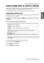
Page 51: ...etwork port 1 After the console is switched on the matrix switch asks you to log in Enter the following data to the login box 2 Press Enter to log in and open the on screen display 3 Press F11 to call the Configuration menu 4 Select Network and press Enter 5 Select Interfaces and press Enter IMPORTANT In the default settings the Network A port is assigned to the IP address 192 168 0 1 Username Ent...

Page 52: ... Press F11 to call the Configuration menu 3 Select Network and press Enter 4 Select Interfaces and press Enter Operational mode Press F8 to select the operating mode of the interface Network A or Network B Off switches off network interface Static uses static settings DHCP obtains the settings from a DHCP server IP address Enter the interface IP address This setting is auto obtained in the DHCP op...

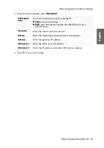
Page 53: ...s Select the operating mode by pressing F8 Static uses static settings DHCP auto obtains the settings described below from a DHCP server Hostname Enter the matrix switch hostname Domain Enter the domain the matrix switch is to belong to Gateway Enter the gateway IP address DNS Server 1 Enter the DNS server IP address DNS Server 2 Enter the IP address of another DNS server option ...

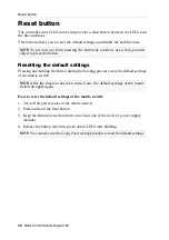
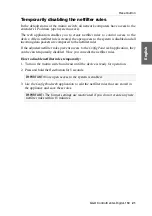
Page 54: ...tch How to reset the default settings of the matrix switch 1 Turn off all power packs of the matrix switch 2 Press and hold the Reset button 3 Keep the button pressed and turn on at least one of the device s power supply modules 4 Release the button when the green Switch LED starts blinking NOTE To prevent you from pressing the button by accident use a thin pointed object to press the button NOTE ...

Page 55: ...d to the netfilter rules If the adjusted netfilter rules prevent access to the Config Panel web application they can be can temporarily disabled Now you can edit the netfilter rules How to disable netfilter rules temporarily 1 Turn on the matrix switch and wait until the device is ready for operation 2 Press and hold the Reset button for 5 seconds 3 Use the Config Panel web application to edit the...

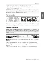
Page 56: ...witching Assigning multiple channels to a console or computer creates a channel group Detailed information on channel grouping can be retrieved in the web application manual EXAMPLE To transmit a second video signal and a USB 2 0 signal of the same computer in addition to the DVI CPU computer module connect a second DVI CPU module second video channel and a U2 CPU module USB2 0 RS232 to the comput...

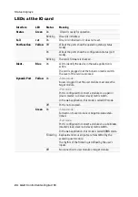
Page 57: ...lue On LED to identify device in the web application is active Name LED Status Meaning Status Green On Controller card is ready for operation Off Controller card is initialised Fail Ctrl Red On The CPU at the controller card does not react Fail Comm Red On The communication module at the controller card does not react Ident Blue On LED to identify the device in the web application is active Networ...

Page 58: ...lever of the card is unlocked Dynamic Port Yellow On Status mode A user is logged in at the user module or accesses the target module Port mode Port is configured to connect a module or a superior slave master sub slave slave matrix switch In the web application this mode is called UP mode Off Port is not occupied Green On Status mode Connection to user module or target module estab lished Port mo...

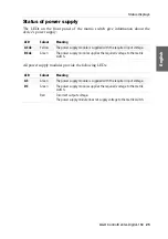
Page 59: ...ng AC ok Yellow The power supply module is supplied with the required input voltage DC ok Green The power supply module supplies the required voltage to the matrix switch LED Colour Meaning AC Green The power supply module is supplied with the required input voltage DC Green The power supply module supplies the required voltage to the matrix switch Red Incorrect output voltage The power supply mod...

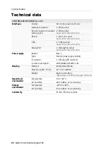
Page 60: ...ure functions DisplayPort 1 DisplayPort socket reserved for future functions Power supply Anzahl Max 3 Type Internal power supply module Connection 1 IEC plug IEC 320 C14 Current consumption 100 240VAC 60 50Hz 3 2A Housing Material Anodised aluminium Dimensions W H D 19 6U 500 mm Weight Approx 20 to 28 kg depending on number and types of IO cards Operational environment Temperature 5 to 40 C Air h...

Page 61: ... English ...

Page 62: ... ...

Page 63: ... English ...

Page 64: ...Obere Leimbach 9 57074 Siegen Germany www gdsys de sales gdsys de Das Handbuch wird fortlaufend aktualisiert und im Internet veröffentlicht The manual is constantly updated and available on our website https gdsys de A9100230 ...

Reviews: