background image

statement 

The  product  has  well  capability  and  intact  packing  when  leave  factory.  All  of  the  user 

should  comply  with  warning  item  and  manual,  any  misuse  cause  of  the  damages  are  not  

included   in   our   guarantee,   and   also   can not   be   responsible   for   any   malfunction   & 

problem owing to ignore the manual. 


1. Safety Instructions 

Please keep this User Guide for future consultation. If you sell the unit to another user, be 
sure that they also receive this instruction booklet. 


Unpack and check carefully there is no transportation damage before using the unit. 


Before  operating,  ensure  that  the  voltage  and  frequency  of  power  supply  match  the 

power requirements of the unit. 


It

’s  important  to  ground  the  yellow/green  conductor  to  earth  in  order  to  avoid  electric 

shock. 


The unit is for indoor use only. Use only in a dry location. 


The  unit  must  be  installed  in  a  location  with  adequate  ventilation,  at  least  50cm  from 

adjacent surfaces. Be sure that no ventilation slots are blocked. 


Disconnect main power before replacement or servicing. 


Make sure there are no flammable materials close to the unit while operating as it is fire 

hazard. 


Use safety cable when fixes this unit. DO NOT handle the unit by taking its head only, but 

always by taking its base. 


Maximum ambient temperature is Ta: 40

. DO NOT operate it where the temperature is 

higher than this Unit surface temperature may reach up to 85

. DO NOT touch the 

housing bare-hand during  its  operation.  Turn  off  the  power  and  allow  about  15  minutes 

for  the  unit  to  cool down before replacing or serving. 


In the event of serious operating problem, stop using the unit immediately.Never try to 

repair the unit by yourself. Repairs carried out by unskilled people can lead to damage 

or  malfunction.  Please  contact  the  nearest  authorized  technical  assistance  center. 

Always use the same type spare parts. 


DO NOT touch any wire during operation as high voltage might be causing electric shock. 

Summary of Contents for G.ems LED Profile 200 WW

Page 1: ...Gush G ems LED Profile 200 WW LED Profile Spot 200W warm white LED User manual ...

Page 2: ...ith adequate ventilation at least 50cm from adjacent surfaces Be sure that no ventilation slots are blocked Disconnect main power before replacement or servicing Make sure there are no flammable materials close to the unit while operating as it is fire hazard Use safety cable when fixes this unit DO NOT handle the unit by taking its head only but always by taking its base Maximum ambient temperatu...

Page 3: ...ing while operating And make sure that the structure to which you are attaching the unit is secure and is able to support a weight of 10 times of the unit s weight Also always use a safety cable that can hold 12 times of the weight of the unit when installing the fixture The equipment must be fixed by professionals And it must be fixed at a place where is out of the touch of people 2 Technical Spe...

Page 4: ... Insert the gobo in the slot 6 Replace fuse Before replacing the fuse unplug mains lead Procedure Step1 Unscrew the fuseholder on the rearpanel with a fitting screwdriver from the housing anti clockwise Step2 Remove the old fuse from the fuseholder Step3 Install the new fuse in the fuseholder Step4 Replacing the fuseholder in the housing and fix it 7 Focus The objective lens cylinder is usually sh...

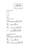
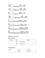
Page 5: ...tion of the keys MENU UP DOWN ENTER 2 Menu Single color display operate DMX512 Address to Slave mode to Master strobe to Dimmer to 3IN1 4IN1 Display Function DMX512 Address to Slave mode to Built in auto mode to ...

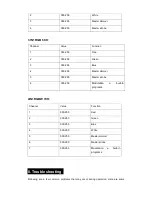
Page 6: ...Master strobe to Red dimmer to Green dimmer to Blue dimmer to White dimmer to DMX Values and Functions Single color 2CH Channel Value Function 1 1 255 Master dimmer 2 1 255 Master strobe 2IN1 WW W 4CH Channel Value Function 1 000 255 Warm white ...

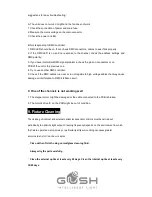
Page 7: ... dimmer 4 000 255 Master strobe Channel Value Function 1 000 255 Red 2 000 255 Green 3 000 255 Blue 4 000 255 Master dimmer 5 000 255 Master strobe 6 000 255 Modulation a built in programs Channel Value Function 1 000 255 Red 2 000 255 Green 3 000 255 Blue 4 000 255 White 5 000 255 Master dimmer 6 000 255 Master strobe 7 000 255 Modulation a built in programs ...

Page 8: ...es run near or run alongside to high voltage cables that may cause damage or interference to DMX interface circuit C One of the channels is not working well 1 The stepper motor might be damaged or the cable connected to the PCB is broken 2 The motor s drive IC on the PCB might be out of condition 9 Fixture Cleaning The cleaning of internal and external optical lenses and or mirrors must be carried...

Reviews: