background image

Working with the Device

mega macs 66

Diagnostics

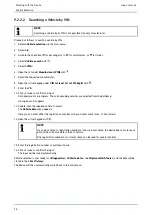
5. Select

>Diagnostics<

in the main menu.

Now you can select the type of diagnostics.

9.4.2

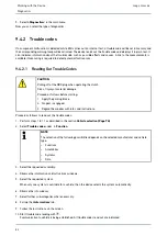
Trouble codes

If a component malfunction is detected while ECU carries out an internal test, a trouble code will be set in memory and
the corresponding warning lamp will be activated. The device reads out the trouble code and displays it in plain text. It
also indicates information about the trouble code, such as possible effects and causes. A link to the measurements is
available if measuring is required to detect potential fault reasons.

9.4.2.1

Reading Out Trouble Codes

CAUTION

Pulling off of the OBD plug when operating the clutch

Risk of injury or material damage

Proceed as follows before starting:

1. Apply the parking brake.

2. No gear is engaged.

3. Regard the window with infos and instructions.

Proceed as follows to read out the trouble codes:

1. Perform steps 1 to 11 as described in the section

Vehicle selection (Page 74)

.

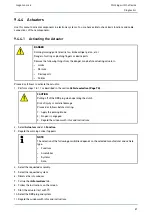
2. Select

Trouble codes

under

> Function

.

NOTE

The selection of the following possibilities depends on the selected manufacturer and vehicle
type:

Functions

Assemblies

Systems

Data

3. Select the requested assembly.

4. Observe the information and instructions windows.

5. Select the requested system.

When only one system is available for a vehicle, then the device selects this system automatically.

6. Observe the info window.

7. Select further sub-categories where necessary.

8. Call up the

>Information<

tab.

9. Follow the instructions on the screen.

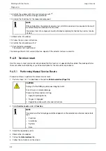
10. Start trouble code reading with

.

Communication to vehicle is being established. All trouble codes read out are indicated.

82

Summary of Contents for mega macs 66

Page 1: ... HBMM66V5400EN0818S0 460 987 74 08 18 User Manual en mega macs 66 Original User Manual ...

Page 2: ... 15 2 2 1 2 Performing Safety Relevant Software Modifications 15 2 2 1 3 Prohibition of Safety Relevant Software Modifications 15 2 2 1 4 Waiver of the Use of Safety Relevant Software Modifications 16 2 2 2 Non Liability 16 2 2 2 1 Data and Information 16 2 2 2 2 Burden of Proof on the User 16 2 2 3 Data Protection 16 2 2 4 Documentation 16 3 Device Description 18 3 1 Delivery Contents 18 3 1 1 Ch...

Page 3: ...g the User Name 30 8 1 2 2 Assigning a Password 30 8 1 2 3 Deleting the Password 31 8 1 2 4 Deleting the User Name 31 8 1 2 5 Activating the Car History 31 8 1 2 6 Setting Up Password Protection 32 8 1 3 Creating Cost Estimates 32 8 2 Updating Device and Modules 32 8 2 1 Preconditions for an Update 33 8 2 2 Calling Up System Information 33 8 2 3 Setting the Language 33 8 2 4 Starting the Test 33 8...

Page 4: ...8 4 6 Setting the Date 44 8 4 7 Setting the Time 44 8 5 Setting Units 45 8 5 1 Assigning Units 45 8 6 Configuring Miscellaneous 45 8 6 1 Configuring the Hardware 45 8 6 1 1 Setting the Display Brightness 45 8 6 1 2 Calibrating the Touch Screen 45 8 6 1 3 Checking the Battery Status 46 8 6 2 Configuring the Car History 46 8 6 2 1 Automatic Car History Transfer 46 8 6 2 2 Manual Parameter Management...

Page 5: ...lues Menu 63 9 1 6 8 Symbols in the Flat Rate Units Menu 64 9 1 6 9 Symbols in the Battery Management Menu 64 9 1 6 10 Symbols in Diesel Systems 64 9 1 7 Symbols in the Measurements Menu 65 9 1 7 1 Symbols in the Cursor Settings Menu 66 9 1 7 2 Symbols in the Trigger Menu 67 9 1 7 3 Setting Symbols in the Measurements Menu 68 9 1 7 4 Symbols in the Measuring Range Menu 69 9 1 8 Symbols in the Appl...

Page 6: ... 9 4 6 3 Performing Automatic Basic Settings 91 9 4 7 Codings 92 9 4 7 1 Performing Manual Coding Procedures 92 9 4 7 2 Performing Automatic Coding Procedures 93 9 5 Vehicle Information 94 9 5 1 Car History 95 9 5 1 1 Selecting Vehicles from the Car History 95 9 5 1 2 Deleting Entries from the Car History 95 9 5 1 3 Deleting Single Entries and the Entire Car History 96 9 5 1 4 All Older Than 96 9 ...

Page 7: ...lator Under Diesel Systems 109 9 5 16 Service information 110 9 5 16 1 Calling Up Service Information 110 9 5 17 Repair instructions 110 9 5 17 1 Calling Up Repair Instructions 110 9 5 18 Manufacturer Campaigns 111 9 5 18 1 Calling Up Manufacturer Campaigns 111 9 5 19 Exhaust Emission Data 111 9 5 19 1 Calling Up Exhaust Emission Data 111 9 6 OBD 112 10 Measurements 113 10 1 Oscilloscope 113 10 1 ...

Page 8: ...e 122 10 1 8 Displaying Recorded Measurements 122 10 2 Guided Measurements 122 10 2 1 Performing Guided Measurements 123 10 2 2 Saving the Guided Measurement 124 10 2 3 Retrieving a Stored Guided Measurement 124 11 Applications 125 11 1 Calculator 125 11 1 1 Activating the Calculator 125 11 2 Emission diagnostics 125 11 2 1 Calling Up Emission Diagnostics 125 11 3 List of alternatives 125 11 3 1 C...

Page 9: ...r Saving Test Results in the Car History 131 12 2 4 Saving Test Results in the Car History 131 13 General Information 132 13 1 PassThru Troobleshooting 132 13 2 Troubleshooting 133 13 3 Care and Maintenance 133 13 4 Disposal 134 13 5 Technical Data of the mega macs 66 135 13 5 1 General Data 135 13 5 2 Diagnostic Module 136 13 5 3 Measurement Module 137 9 ...

Page 10: ...sively deal with your safety during the work with the device When working with the device it is recommended to read the individual work steps in the manual again to prevent hazard of persons and equipment or operating errors The device shall be used exclusively by a qualified person Information and knowledge included this training is not explained in this user manual The manufacturer reserves the ...

Page 11: ...d NOTICE refer to a hazard in the device or environment Therefore it is absolutely necessary to observe the notes or instructions stored here NOTE Texts marked with NOTE contain important and helpful information It is recommended to observe these texts Crossed out waste bin This label indicates that the product must not be discarded as domestic waste The bar underneath the waste bin indicates whet...

Page 12: ...sures and safety precautions must also be followed Furthermore pay attention to all general instructions from labor inspectorates trade associations and vehicle manufacturers as well as all laws legal ordinances and instructions which have to be commonly obeyed by a repair shop 2 1 2 Safety Precautions Risk of Injury When working on the vehicle there is a risk of injury through rotating parts or r...

Page 13: ... of the device or if the protective seal is damaged If the device malfunctions contact Hella Gutmann or a Hella Gutmann trading partner without delay 2 1 4 Safety Precautions for High Voltage Line Voltage Very high voltages occur in electrical systems Due to voltage flashover on damaged components such as marten damage or touching live components the risk of electric shock is likely High voltage v...

Page 14: ...the service disconnect plug safe or secure the battery master switch against re activation Insulate the battery master switch the plug connections etc with dummy plugs covering caps or insulating tape with the corresponding warning notice Check the de energized state with a voltage tester Even with disconnected high voltage system residual voltage can still be present Ground and short circuit the ...

Page 15: ...o include components in safety related vehicle systems e g airbag or brakes The following notes and instructions also apply to future updates and related software extensions 2 2 1 2 Performing Safety Relevant Software Modifications Work on safety related areas e g the occupant safety system and the brake system is only allowed to be performed if the user has read and accepted this note The user of...

Page 16: ...e data 2 2 2 2 Burden of Proof on the User The burden of proof is on the user of the device that he has paid attention to technical explanations notes on operation equipment care as well as maintenance and safety without exception 2 2 3 Data Protection The Customer agrees that its data may be stored for implementing and executing the contractual relationship and that technical data may be stored f...

Page 17: ...r Information Non Liability The burden of proof is on the user of the device that he has paid attention to technical explanations notes on operation equipment care as well as maintenance and safety without exception 17 ...

Page 18: ...hecking Delivery Contents Please check the delivery contents upon receiving your device so that complaints can be issued immediately regarding any potential damage Proceed as follows to check the delivery contents 1 Open the package supplied and check for completeness based on the delivery slip Should you identify any damage to the package then open the package in the presence of the delivery serv...

Page 19: ...service data set values and descriptions of vehicle systems A lot of this data is transferred to the device directly from the Hella Gutmann diagnostic database via online connection Therefore the device must be permanently online The device is not suitable for repairing electrical machines and equipment or home electrics Diagnostic devices from other manufacturers will not be supported If the devi...

Page 20: ...nabled by acquiring a corresponding license subject to charge and or additional hardware 3 5 Display D De es si ig gn na at ti io on n 1 TFT LCD touch screen 2 Stylus 3 5 1 Operating the Device NOTICE Damage or destruction of the display Never touch the display using a tool or pointed metal object Always use the stylus or a finger The device is equipped with a touch screen display All menus and fu...

Page 21: ...cket Power supply of the device and internal battery charge connection 9 Diagnostic module DT 66 Use the DT 66 to diagnose the automotive electronics and to forward the data to the device 10 Green LED The green LED signals the communication module is switched on and ready 11 ON OFF button Switch on or off the diagnostic module if it is not plugged into the module slot 12 Parallel port Connect the ...

Page 22: ... es si ig gn na at ti io on n 18 Positioning handle Use the handle to set up the device carry it or fix it to the steering wheel in the vehicle Internal 1x WLAN 2x Bluetooth module All wireless connections are integrated in the device and are permanently switched on 22 ...

Page 23: ... provided by Hella Gutmann the device requires a permanent online connection and the installed driver package Hella Gutmann Drivers To keep the connection costs down Hella Gutmann recommends a DSL connection and a flat rate 1 Install the Hella Gutmann Drivers on the office or repair shop PC The driver package Hella Gutmann Drivers program is on the supplied HGS data carrier 2 Connect the device to...

Page 24: ...n of the software varies depending on the manufacturer The following options are available Download the PC software Request the PC software on CD or DVD Online solutions Here charges may accrue depending on the manufacturer e g for Registration Licenses Software The software content scope of information and function varies depending on the manufacturer Some manufacturers provide the legally requir...

Page 25: ...arget directory 7 Click the PassThru setup exe in the target directory The window HGS PassThru Setup is displayed 8 Select the requested language with 9 Confirm the selection with OK The selection is saved automatically The setup wizard of HGS PassThru is displayed 10 Click Next The general terms and conditions GTCs appear 11 Read the GTCs and confirm them at the end of the text 12 Click Next Sele...

Page 26: ...Thru Software CAUTION Pay attention that the voltage supply during the entire procedure is no lower than 12 V A voltage drop may lead to the abortion of the download and the ECU may be damaged The old software version of the ECU cannot be re established if an update is intended NOTE The diagnostic module DT 66 must be inserted in the module slot of the mega macs 66 Proceed as follows to run the HG...

Page 27: ...Thru software as follows Windows 7 Select the HGS PassThru shortcut in the desktop 10 Select the requested language 11 Start the communication test with Start test The communication test is started Connection between laptop tablet and HGS PassThru device is tested The connection between laptop tablet and HGS PassThru device is active if the left row of arrows is green The connection between HGS Pa...

Page 28: ... confirm the general terms and conditions GTC of the Hella Gutmann Solutions GmbH Otherwise certain device functions will be unavailable Proceed as follows to switch on the device 1 Press in main switch until it latches in The device switches to standby mode 2 Slightly touch the display The GTCs appear 3 Read the GTCs and confirm them at the end of the text The user selection window is displayed T...

Page 29: ...d is in progress Purchased licenses are displayed 4 Switch the device off and on again Now you can start working with the device 7 4 Switching off the Device NOTE Under normal conditions it is sufficient to switch off the device with For transport and storage the device must be switched off with the main switch so that it cannot be switched on unintentionally Proceed as follows to switch off the d...

Page 30: ... steps 3 5 for further entries 8 1 2 User name 8 1 2 1 Entering the User Name Here you can manage the different users The respective user name is saved for all data stored in the Car History This enables quicker identification of the mechanic who performed the repair work if a query is subsequently made Proceed as follows to enter the user name 1 Select Company under Settings in the main menu 2 Se...

Page 31: ...prompt 6 Confirm the confirmation prompt with Password will be deleted 8 1 2 4 Deleting the User Name Proceed as follows to delete the user name 1 Select Company under Settings in the main menu 2 Select User 3 Select the required user name 4 Delete the user name with 5 Observe the confirmation prompt 6 Confirm the confirmation prompt with The user name is deleted 8 1 2 5 Activating the Car History...

Page 32: ...word and confirm by entering it again 5 Observe the warning notice and confirm The device can now be accessed only with the selected password 8 1 3 Creating Cost Estimates Here you can enter the base values for the cost estimate You can enter 3 different hourly rates net and one VAT rate These values are used to calculate the total amount of the work to be done Proceed as follows to enter the basi...

Page 33: ... device number 8 2 3 Setting the Language Here you can set the language version if the software is multilingual After having set the language the update will be installed in this language Proceed as follows to set the language 1 Select Update under Settings in the main menu 2 Select System 3 Open the list under Language setting with The compilation of languages depends on the prevailing software 4...

Page 34: ...cs 66 has three module slots The first one is intended for the DT 66 diagnostic module the second one is intended for the MT 66 measurement module and the third one is a secondary slot for further modules NOTE The module update for the DT 66 can also be performed wirelessly via Bluetooth If an obsolete version of the module software is detected at the start of the diagnostics then a corresponding ...

Page 35: ...t the printer language PCL5 or higher and that has a USB port In order to ensure trouble free support through the Technical Help Line we recommend using a printer of Hella Gutmann Proceed as follows to print out results via USB port 1 Plug in the USB cable not included in the contents of delivery to the device s and the printer s USB port 2 Select Interfaces under Settings in the main menu 3 Selec...

Page 36: ...d height of the margins in mm 8 Confirm your entry with The input will be saved automatically 9 Repeat steps 5 8 for further entries 10 Where necessary activate the check box Blank out company logo to print out results without the company logo of Hella Gutmann This function enables hard copy printouts on printed paper Now you can start printing via PC 8 3 2 Configuring the BPC Tool 8 3 2 1 Searchi...

Page 37: ...off the device and the BPC Tool during the update and do not disconnect them from the voltage supply Ensure sufficient voltage supply 4 Start BPC Tool update with 5 Regard the window with infos and instructions 6 Confirm the window with infos and instructions with Update of the BPC Tool will start The device searches for a new update that will then be downloaded and installed The message BPC Tool ...

Page 38: ...rivers is installed 8 3 4 1 Searching for the Bluetooth Adapter NOTE If the device has already been delivered with a Bluetooth adapter both devices are already assigned to each other ex works Proceed as follows to search for the Bluetooth adapter 1 Insert the Bluetooth adapter into the USB port of the PC 2 Select Interfaces under Settings in the main menu 3 Select the Bluetooth tab 4 Activate the ...

Page 39: ...confirmation prompt with 6 Disconnect the Bluetooth adapter connection and delete the assignment with 7 Observe the confirmation prompt 8 Confirm the confirmation prompt with The Bluetooth adapter connection is disconnected and the assignment is deleted 8 3 4 3 Performing Bluetooth Diagnostics Proceed as follows to perform Bluetooth diagnostics 1 Insert the Bluetooth adapter into the USB port of t...

Page 40: ...7 Select Determine automatically DHCP or Determine manually The selection will be saved automatically 8 Create wireless network with The device searches for wireless networks Once the device has successfully finished searching for wireless networks a drop down list of wireless networks found is then displayed 9 Select the requested wireless network 10 Regard the window with infos and instructions ...

Page 41: ...rders due to foreign providers Therefore determine the provider manually where required Proceed as follows to connect the device via the UMTS interface 1 Disconnect the USB Ethernet cable from the device 2 Select Interfaces under Settings in the main menu 3 Select UMTS 4 Activate the check box to be able to do the settings A confirmation prompt appears if either the Bluetooth adapter or WLAN was p...

Page 42: ...r the provider 18 Select Automatically Roaming or Determine manually 19 Observe the confirmation prompt 20 Affirm the confirmation prompt with 21 Open the list under Access Point Name APN with NOTE The provider offers a certain access point indicated through the APN which depends on the applicable data tariff If the APN is unknown please contact the mobile provider concerned to obtain the necessar...

Page 43: ...switches off automatically The language setting will be saved automatically The device switches on again and automatically switches to standby mode 6 Slightly touch the display 7 Confirm the user selection window with The main menu appears 8 4 2 Making Country Settings Make your country settings here The country version contains certain information such as the print format for letters Proceed as f...

Page 44: ...eed as follows to set the time format 1 Select Country under Settings in the main menu 2 Open the list under Time format with 3 Select 24 h or 12 h The selection will be saved automatically 8 4 6 Setting the Date Here you can set the present date Proceed as follows to set the date 1 Select Country under Settings in the main menu 2 Open the drop down list under Date with 3 Open the list under Day w...

Page 45: ...gs such as Display brightness Demo mode Order management 8 6 1 Configuring the Hardware Here you can calibrate the display brightness and the touch screen and you can set the status of the rechargeable battery 8 6 1 1 Setting the Display Brightness Proceed as follows to set the display brightness 1 Select Miscellaneous under Settings in the main menu 2 Select Hardware 3 Open the list under Brightn...

Page 46: ...Parameters Basic settings and Codings This has the following advantages You can evaluate the diagnostic results later Compare previously performed diagnostics to present diagnostic results You can show the customer the diagnostic results without needing to reconnect the vehicle 8 6 2 1 Automatic Car History Transfer NOTE Only if Automatic Car History transfer is set to on the data saved in the Car...

Page 47: ...to on With the Parameter management function you can delete parameter records from the Car History This is useful if more memory space is required for further parameter records Proceed as follows to delete parameter records 1 Select Miscellaneous under Settings in the main menu 2 Select Car History 3 Call up Parameter management with An info and selection window appears Deactivate all parameter re...

Page 48: ...n menu 2 Select Miscellaneous 3 Open the list under Demo mode with 4 Select on or off Demo mode is switched off or on 8 6 3 2 Setting Tips Here you can activate or deactivate additional information on different functions Proceed as follows to set the indication of tips 1 Select Miscellaneous under Settings in the main menu 2 Select Miscellaneous 3 Open the list under Tips with 4 Select on or off T...

Page 49: ... such as company data The following functions will be also modified or deleted IP address mode Telekom HotSpot Bluetooth MAC address asanetwork Display settings Confirmation of General terms and conditions Printer settings Proceed as follows to perform a factory reset 1 Select Miscellaneous under Settings in the main menu 2 Select Miscellaneous 3 Select Start factory reset with 4 Observe the confi...

Page 50: ...ograms and functions used by the Hella Gutmann Solutions GmbH 8 7 1 Retrieving the License Here you can see an overview of the purchased licenses Proceed as follows to retrieve licenses 1 Select Contracts under Settings in the main menu 2 Select License 3 Call up My licenses with Data download is in progress Purchased licenses are displayed 8 7 2 Displaying the GTC Here you will find the general t...

Page 51: ...to the module slot The OBD plug is not inserted into the vehicle s diagnostic interface 8 8 2 Performing an OBD Plug Test This test serves as function check of the OBD plug for defects Proceed as follows to perform the test functions 1 Select Test functions under Settings in the main menu 2 Call up OBD plug test with 3 Regard the window with infos and instructions 4 Start the test with OBD plug te...

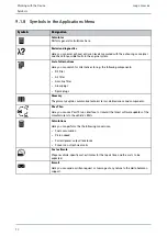
Page 52: ...rt the selected function Confirm the present entry Confirm your menu selection Cancel Cancel the following functions Active function Input Start Start a function or procedure Delete Delete data or entries Arrow keys Navigate with the cursor in menus or functions Print Print the current window Help Open the user manual and explanations on the individual menus or functions Virtual keypad Open the vi...

Page 53: ... Device Symbols S Sy ym mb bo ol ls s D De es si ig gn na at ti io on n Select all Select all available elements Unselect all Unselect all available elements Zoom in Zoom in the present view Zoom out Zoom out of the present view 53 ...

Page 54: ...following information Quantity Component name Manufacturer Item number The shopping cart symbol is dark if there are spare parts in the cart Order network This network is used for data exchange between device and order network Mail box The incoming e mails and help calls are stored here The symbols indicate an incoming e mail or help call Envelope symbol No new e mails Envelope symbol with exclama...

Page 55: ...T modules The symbol shows the active connection Black symbol Connection to the DT modules is inactive Green symbol At least 1 connection to the DT module is active PC connection status Here you can view the active and inactive interfaces between the device and the PC e g USB Ethernet WLAN The symbol shows the active interface Black symbol No interface is active Green symbol At least 1 interface i...

Page 56: ...Assistance in finding the installation location of a component Timing belt and service data Technical Data Wiring diagrams Recall campaigns of vehicle manufacturers and importers Measurements This menu contains the 2 channel oscilloscope and the guided measurements with automatic signal evaluation The 2 channel oscilloscope supports the following measured variables Voltage Resistance Current Tempe...

Page 57: ...aved diagnostic data records on a certain vehicle VIN identification Read out the VIN of the vehicle using the OBD plug OBD diagnostics Here you can only start the OBD diagnostics by selecting the vehicle manufacturer and the fuel type Page forward Go one page forward Page back Go one page back Information Call up additional information regarding the selected vehicle e g Vehicle type Engine displa...

Page 58: ... you can close a print preview after a global check of the trouble codes Sending a Call for Help Contact the Technical Help Line and request data here Selection to the right Add available individual parameters to the selected parameters here Selection to the left Relocate single parameters back to the list of available parameters here Select all Relocate all parameters selected back to the list of...

Page 59: ...data This menu contains the removal and installation instructions for timing belts and timing chains Diagnostic Database This menu contains manufacturer and vehicle specific solutions for various problematic cases All suggested solutions are from the practice and are retrieved from the Hella Gutmann diagnostics database Technical Data Here you can find all of the data required for service and repa...

Page 60: ...paigns This menu contains the recall campaigns of manufacturers and importers Battery management Here you can test the battery with the BPC Tool Diesel systems Here you can find the service work for diesel particulate filters Service information This menu contains all the service information required for certain service work e g Electrics Suspension Accessory parts Repair instructions Here you can...

Page 61: ...Previous entry Here you can call up the previous entry in the Car History Add data inquiry or symptom Add another data inquiry or a further symptom to a help call Call for help memory View all the stored helps calls here 9 1 6 2 Symbols in the Component Help Menu S Sy ym mb bo ol ls s D De es si ig gn na at ti io on n Search a component Search a certain component by its name in the component help ...

Page 62: ...m the service database Component list Here you can call up a list with context relevant components Additional information Here you can view additional vehicle information about the manufacturer model or type Select service interval Here you can find and select the vehicle specific service intervals of the vehicle Back to flat rate units Here you can return to the general flat rate units and times ...

Page 63: ... Indicating blanking the general view of the wiring diagram If you zoomed the wiring diagram you can view an overview bottom left If you move the frame in general view you can view the section in the zoomed view Component help Here you can find additional information on the selected component e g Wiring diagrams Parts information 9 1 6 6 Symbols in the Fuses Relays Menu S Sy ym mb bo ol ls s D De ...

Page 64: ...icable you can see additional work steps that can arise during work here 9 1 6 9 Symbols in the Battery Management Menu S Sy ym mb bo ol ls s D De es si ig gn na at ti io on n Display explanation Here you can call up explanations for the test result and the specialist terms to be used 9 1 6 10 Symbols in Diesel Systems S Sy ym mb bo ol ls s D De es si ig gn na at ti io on n Call up the calculator ...

Page 65: ...ment Save the performed measurement here Settings Make various settings for signal acquisition and the output of values Adjust cursor Open functions for the cursor setting here Cursor position Measuring Signals Cursor settings Trigger Open the functions for the trigger setting The trigger fixes a voltage point of the signal and always displays that point at the same position on the monitor The tri...

Page 66: ...rt over Start the measurement Change from the display of a stored measurement directly to Oscilloscope 9 1 7 1 Symbols in the Cursor Settings Menu S Sy ym mb bo ol ls s D De es si ig gn na at ti io on n Place the cursor Here you can move the cursor Measuring Signals Use these keys to set the current x and y cursor position as start mark to the signal so that a signal range can be measured afterwar...

Page 67: ...rigger Menu S Sy ym mb bo ol ls s D De es si ig gn na at ti io on n Place the trigger Move the trigger here Set the trigger level Set the trigger level here Trigger settings Perform the following trigger settings Trigger channel Trigger mode Trigger edge Trigger level 67 ...

Page 68: ...the maximum distance between the upper and lower signal peak of the entire measuring process Frequency View the signal frequency here Period duration View the duration of a signal period here On off ratio Here you can view the percentage signal to noise relation duty cycle of the time the signal is switched on and switched off One signal period is One signal period is 100 This indication mode is s...

Page 69: ... positive voltage values Measuring range calibration Set the voltage curve on the zero line In this way you can compensate for interference voltages and measuring range tolerances Set value windows to zero position Here you can set the following value windows to zero simultaneously so that only future values will be taken into account Minimum Maximum Peak to peak Auto Set Analyze the incoming sign...

Page 70: ... filter Air filter Gasoline filter Glow plugs Spark plugs Glossary The glossary explains automotive technical terms abbreviations and components Pass Thru Here you can use PassThru as interface to transmit the latest software updates of the manufacturers to the vehicle s ECUs Calculations Here you can perform the the following conversions Fuel consumption Piston speed Current power output resistan...

Page 71: ...earch for components and abbreviations via search term Component information Here you can find explanations to the selected component or the selected abbreviation 9 1 8 3 Symbols in the Cost Estimate Menu S Sy ym mb bo ol ls s D De es si ig gn na at ti io on n Add a cost estimate Add a new cost estimate or another category of an existing cost estimate Save cost estimate Save the present cost estim...

Page 72: ... Answer an e mail directly Write new e mail Here you can write a new e mail to the Hella Gutmann Technical Help Line Refreshing messages Refresh the overview of e mails and help calls Inbox Indication of received e mails Sent e mails Indication of sent e mails Deleting e mails Junk mail Delete e mails or get an overview of deleted e mails 72 ...

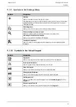
Page 73: ...pter Here you can search for the Bluetooth adapter Language management Uses this symbol to set language specific keypad layouts and to delete installed languages 9 1 10 Symbols in the Virtual Keypad S Sy ym mb bo ol ls s D De es si ig gn na at ti io on n Copy paste Here you can copy text into the clipboard or paste text from the clipboard Insert special characters Use this symbol to insert special...

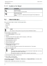
Page 74: ...r for trucks 4 Select Vehicle database with or 5 Select the requested manufacturer 6 Select the requested fuel type 7 Select the requested model 8 Double click to the requested vehicle type The Vehicle data menu appears Here you can enter either the registration number or the customer name max 10 characters 9 Open the virtual keypad with NOTE If you do not enter a registration number or the custom...

Page 75: ...nics Switch off the ignition before connecting the ST2 and data link connector 5 Insert the ST2 connector into the ST2 socket of the DT 66 CAUTION Pulling off the OBD plug when operating the clutch Risk of injury or material damage Proceed as follows before starting 1 Apply the parking brake 2 No gear is engaged 3 Regard the window with infos and instructions NOTICE Short circuit and voltage peaks...

Page 76: ...a menu appears Here you can enter either the registration number or the customer name max 10 characters 14 Open the virtual keypad with NOTE If you do not enter a registration number or the customer name the device does not store any data of the current vehicle in the Car History One registration number or customer name can be used for several vehicles 15 Enter the registration number or customer ...

Page 77: ...search criteria are adapted on a country specific basis 8 Open the virtual keypad on the first search criterion with 9 Enter the requested value 10 Confirm your entry with 11 Repeat steps 8 to 10 for the second search criterion where necessary 12 Start the country specific search with Data download is in progress The corresponding vehicles are selected from the database A drop down list appears 13...

Page 78: ...corresponding vehicles are selected from the database A drop down list appears 11 Double click the required vehicle to select The Vehicle data menu appears Here you can enter either the registration number or the customer name max 10 characters 12 Open the virtual keypad with NOTE If you do not enter a registration number or the customer name the device does not store any data of the current vehic...

Page 79: ...ick twice to confirm the input Data download is in progress The corresponding vehicles are selected from the database A drop down list appears 9 Double click the required vehicle to select The Vehicle data menu appears Here you can enter either the registration number or the customer name max 10 characters 10 Open the virtual keypad with NOTE If you do not enter a registration number or the custom...

Page 80: ...at have to be checked The respective scope of inspection and variety of functions depend on the intelligence of the vehicle system The following parameters are available under Diagnostics Trouble codes Here you can read out and delete trouble codes stored in the ECU memory Information on the fault code are available too Measured value Here the device indicates the present flat rate units or states...

Page 81: ...nostics 1 Perform steps 1 to 11 as described in the section Vehicle selection Page 74 2 Take the diagnostic module DT 66 out of the mega macs 66 NOTICE Short circuit and voltage peaks when connecting the ST2 and data link connector Danger of destruction of automotive electronics Switch off the ignition before connecting the ST2 and data link connector 3 Insert the ST2 connector into the ST2 socket...

Page 82: ...ceed as follows before starting 1 Apply the parking brake 2 No gear is engaged 3 Regard the window with infos and instructions Proceed as follows to read out the trouble codes 1 Perform steps 1 to 11 as described in the section Vehicle selection Page 74 2 Select Trouble codes under Function NOTE The selection of the following possibilities depends on the selected manufacturer and vehicle type Func...

Page 83: ...Reading out trouble codes Page 82 NOTE All trouble codes selected will be irrevocably deleted from the ECU memory after the deletion process Therefore always save the read out data read in the Car History 2 Clear the saved trouble codes from the vehicle system with All trouble codes in the ECU memory will be cleared The message Trouble code deletion done appears if the trouble codes have been clea...

Page 84: ...st of the individual trouble codes for the respective ECU with You can close the print preview with a list of the individual trouble codes for the respective ECU with 10 Call up the required trouble codes under Faults in the respective ECU memory with The device indicates all trouble codes and repair tips 9 4 2 4 Global Check Trouble Code Clearing Here you can clear all the trouble codes stored in...

Page 85: ...ty In both cases diagnostics can be significantly eased if the corresponding parameters are read out The mega macs 66 reads the parameters and displays them in plain text It additionally provides information on the parameters 9 4 3 1 Reading Out Parameters NOTE Calling up the ECU parameters for the fault diagnostics after the trouble codes have been read has priority over all other work steps Proc...

Page 86: ...ect the requested parameter group under Groups Diagnose a certain problematic case directly by selecting a parameter group as only the parameters required for it are stored 15 Select additionally required parameters in the list Available parameters by double clicking if required You can select maximum 16 parameters at the same time 16 Start the parameter reading with During the readout procedure t...

Page 87: ...d in the section Vehicle selection Page 74 CAUTION Pulling off of the OBD plug when operating the clutch Risk of injury or material damage Proceed as follows before starting 1 Apply the parking brake 2 No gear is engaged 3 Regard the window with infos and instructions 2 Select Actuators under Function 3 Regard the warning notice if appears NOTE The selection of the following possibilities depends ...

Page 88: ...set Use this menu to reset service intervals provided that this function is supported by the vehicle The device performs the resets either automatically or you find a description for the manual reset procedure 9 4 5 1 Performing Manual Service Resets Proceed as follows to perform the manual service reset 1 Perform steps 1 to 11 as described in the section Vehicle selection Page 74 CAUTION Pulling ...

Page 89: ...ly the parking brake 2 No gear is engaged 3 Regard the window with infos and instructions 2 Select Service resets under Function NOTE The selection of the following possibilities depends on the selected manufacturer and vehicle type Functions Assemblies Systems Data 3 Select the requested system 4 Observe the info window 5 Call up the Information tab 6 Follow the instructions on the screen 7 Start...

Page 90: ...t vehicle type Regard the window with infos and instructions Proceed as follows to perform the manual basic setting 1 Perform steps 1 to 11 as described in the section Vehicle selection Page 74 CAUTION Pulling off of the OBD plug when operating the clutch Risk of injury or material damage Proceed as follows before starting 1 Apply the parking brake 2 No gear is engaged 3 Regard the window with inf...

Page 91: ...ng off of the OBD plug when operating the clutch Risk of injury or material damage Proceed as follows before starting 1 Apply the parking brake 2 No gear is engaged 3 Regard the window with infos and instructions 2 Select Basic settings under Function NOTE The selection of the following possibilities depends on the selected manufacturer and vehicle type Functions Assemblies Systems Data 3 Select t...

Page 92: ...ge of the vehicle or the ambient area Regard the following when performing coding procedures Some working procedures require a specific training e g working on the airbag Regard the window with infos and instructions Proceed as follows to perform manual coding 1 Perform steps 1 to 11 as described in the section Vehicle selection Page 74 CAUTION Pulling off of the OBD plug when operating the clutch...

Page 93: ...rform steps 1 to 11 as described in the section Vehicle selection Page 74 CAUTION Pulling off of the OBD plug when operating the clutch Risk of injury or material damage Proceed as follows before starting 1 Apply the parking brake 2 No gear is engaged 3 Regard the window with infos and instructions 2 Select Codings under Function NOTE The selection of the following possibilities depends on the sel...

Page 94: ...ndicates the location of the main fuse box the fuse box and the relay box in the vehicle depending on the selection Timing belt data Here you can retrieve the tools required for repairing the timing belt as well as the vehicle specific removal and installation instructions via the Hella Gutmann Drivers Diagnostic Database Here you can retrieve vehicle specific online assistance via the Hella Gutma...

Page 95: ... advantages You can evaluate the diagnostic results later Compare previously performed diagnostics to present diagnostic results You can show the customer the diagnostic results without needing to reconnect the vehicle 9 5 1 1 Selecting Vehicles from the Car History NOTE Diagnostic results automatically stored here can be retrieved only if the function Automatic Car History Transfer is set to on u...

Page 96: ...ntries will be deleted 9 5 1 5 Sending a Help Call Contact the Technical Help Line and request data here Proceed as follows to send a help call to the Hella Gutmann Technical Help Line 1 Select Vehicle information in the main menu 2 Call up the Car History with 3 Select the requested Car History file with 4 Call up the Help call with 5 If necessary open a list under Contact person with and select ...

Page 97: ... Technical Help Line check box A Hella Gutmann colleague will call you back as soon as possible 10 Continue with 11 Open the virtual keypad under VIN Vehicle Identification Number with 12 Enter the VIN 13 Confirm your entry with 14 Open the selection window under First registration with 15 Open the list under Day with 16 Select the day of the first registration 17 Repeat steps 15 and 16 for Month ...

Page 98: ...quired contact person NOTE You need to enter a telephone number and to tick at least one of the check boxes to be able to continue 6 Open the virtual keypad under Call back number with 7 Enter the required telephone number 8 Confirm your entry with 9 Activate the check box What do you want to do activate the Request data check box 10 Continue with 11 Open the virtual keypad under VIN Vehicle Ident...

Page 99: ...d Use to go back one step and change previous entries 29 Send a help call with Car History data will be transferred 9 5 2 Component help Here you can find the components that are installed in the selected vehicle The following are available Components relevant for diagnostics Here you can find the components that are installed in the selected vehicle and relevant for diagnostic work Parts catalog ...

Page 100: ...with cables connected to an ECU plug You will leave the Component help menu when selecting Component test values Return to the Component help with Fuses relays Here you can view the installation position of the main fuse box the fuse box and the relay box as well as the individual fuses Leave the component help menu by selecting Fuses relays Return to the Component help with Service data This menu...

Page 101: ...ry 10 Activate the check box for the processed working positions 11 Enter the tire tread depth and the tire pressure under Further points after having done all working positions 12 Open the virtual keypad under mm with 13 Enter the tire tread depth 14 Confirm your entry with 15 Repeat steps 12 to 14 for further entries 16 Open the virtual keypad under bar with 17 Enter the tire pressure 18 Confirm...

Page 102: ...red for removal and installation Removal Instructions This displays text and images for the individual work steps for the removal process Installation instructions This displays text and images for the individual work steps for the installation process NOTE If multiple removal and installation instructions appear these are indicated with numbers e g Removal 1 Removal 2 Installation 1 You need to c...

Page 103: ...a download is in progress 6 Select further components or symptoms if necessary 7 Confirm the selection with Data download is in progress 8 Select the required Item from online diagnostic database from the left selection window 9 Select the requested proposal for solution with An info window appears Here you can view the following information Cause NOTE Solution Possibly defective component 10 Repe...

Page 104: ...t the end of the text Just click to view this information 9 5 7 Wiring diagrams View a vast number of vehicle specific wiring diagrams here 9 5 7 1 Calling Up Wiring Diagrams NOTE You need an online connection to access the wiring diagrams NOTE The selection of the following possibilities depends on the selected manufacturer and vehicle type Functions Assemblies Systems Data Proceed as follows to ...

Page 105: ...se box and or the relay box The right hand window displays an overview of the fuse or relay box The top left window indicates the installation position of the fuse or relay box in the vehicle with a red circle The relays are marked with grey rectangles Fuses are marked with colored rectangles 4 Selected the required fuse or relay by clicking it If the position of the fuse or relay is unknown you c...

Page 106: ...Select the required information Image and text information is displayed 9 5 10 Flat rate units Here you can view the common labor rates and repair times on different components 9 5 10 1 Calling Up Flat Rate Units NOTE You need an online connection to access the flat rate units Proceed as follows to retrieve flat rate units 1 Select Vehicle information in the main menu 2 Select Flat rate units with...

Page 107: ...filter Proceed as follows to call up the removal instructions for the cabin air filter 1 Select Vehicle information in the main menu 2 Select Cabin air filter with The removal instructions appear The removal instructions appear as individual images in the left hand window A large format version of the selected image appears in the right hand window 3 Click the images on the left from top to bottom...

Page 108: ...agement with 3 Select Battery diagnostics 4 Regard the window with infos and instructions 5 Select the requested parameter under Diagnostic type 6 Repeat step 5 for another selection 7 Activate the BPC Tool connection see operating instructions of BPC Tool 8 Start the battery diagnostics with Connection toBPC Tool is being established The device will close the info window automatically after a cou...

Page 109: ...ormation in the main menu 2 Select Diesel systems with 3 Select Diesel diagnostics 4 Select Diesel system or Diesel particulate filter 5 Confirm the selection with The Diesel system is indicated as image information 6 Select the requested component by clicking on it If you do not know the position of a component you can select the component directly with The component is indicated by a colored fra...

Page 110: ... information 1 Select Vehicle information in the main menu 2 Select Service information with 3 Select the required information 4 Repeat step 3 for another selection 5 Confirm the selection with Texts and images appear for every information selected 6 Click the images on the left from top to bottom consecutively Available images are indicated in large format The image that is currently clicked is m...

Page 111: ... Select the requested criterion 4 Repeat step 3 for another selection 5 Confirm the selection with Data download is in progress The manufacturer campaigns appear 9 5 19 Exhaust Emission Data This menu contains the nominal exhaust emission values determined by the manufacturer and the test steps necessary for a German exhaust emission check 9 5 19 1 Calling Up Exhaust Emission Data NOTE You need an...

Page 112: ...ame data Indication of ambient data rpm coolant temperature of the stored fault code Permanent trouble codes Indication of all permanent trouble codes that are emission relevant Delete trouble codes Deletion of all trouble codes from Mode 2 3 7 Oxygen sensor test results Check and evaluation of oxygen sensor function This mode is not supported at CAN bus protocols Result of sporadic system test In...

Page 113: ...he Hella Gutmann infrared thermometer for temperature measurements For pressure measurements you must use the Hella Gutmann Low Pressure Diagnostic Kit LPD kit A light blue bar in the top toolbar indicates how much of the memory space reserved for this purpose in the Car History has been used If the blue bar is complete the first data of the present measurement will be removed from the memory and ...

Page 114: ...nsert the test lead into MT 66 and connect it to the relevant component 2 Select Measurements in the main menu 3 Select the Oscilloscope tab 4 Activate the check box for the desired measured variable and the oscilloscope channel 5 Confirm the selection with Measurement will be started 10 1 2 3 Connecting the Current Clamp to the Vehicle and the MT 66 10 1 2 4 Measuring Current Proceed as follows f...

Page 115: ...e cables or with the arrow pointing away from the battery around all negative cables respectively Current will be measured 10 1 2 5 Measuring the Temperature Temperature can be measured with the Hella Gutmann infrared thermometer regardless of the device used see operating instructions for infrared thermometer However the Hella Gutmann infrared thermometer must be connected to the device via the s...

Page 116: ...er 8 Start the calibration with The signal will be calibrated 9 Go one step back with Temperature will be measured 10 1 2 6 Pressure Measurements Proceed as follows for pressure measurements 1 Select Measurements in the main menu 2 Select the Oscilloscope tab The window for measured variables and channels appears 3 Insert the electrical plug connection of the LPD kit into the ST3 connector of the ...

Page 117: ...up or down e g to measure negative voltage 4 Go one step back with 10 1 3 2 Automatic Setting of Measuring Ranges If resistance is measured then the measuring range cannot be set automatically Proceed as follows to set the measuring ranges for voltage current temperature and pressure while measurement is in progress 1 Start Auto Set with NOTE If the measurement signal changes during the ongoing me...

Page 118: ...n to the left or to the right Proceed as follows to set the trigger position while measurement is in progress 1 Open the trigger settings with The bottom toolbar is adjusted The trigger position is identified by a blue cross 2 Set the trigger position with You can also click in the signal depiction to set the trigger position 3 Go one step back with 10 1 4 2 Setting the Trigger Mode With the trigg...

Page 119: ...onfirm the selection with The selection will be saved automatically 10 1 4 4 Setting the Trigger Level The trigger level controls the voltage point at which triggering takes place The trigger level is set to automatic by default ex works NOTE To modify the trigger level expert mode must be set to on Proceed as follows to set the trigger level manually while measurement is in progress 1 Call up Set...

Page 120: ...erential values of both measuring points in the left value windows 6 Repeat steps 2 to 5 for further entries where necessary 7 Go one step back with 10 1 5 3 Zero Reset of Values Here you can set the following value windows to zero simultaneously Minimum Maximum Peak to peak Proceed as follows to set the value window to zero while measurement is in progress 1 Reset the values to zero with The sele...

Page 121: ... the alternator Proceed as follows to set the coupling while measurement is in progress 1 Call up Settings with 2 Select Miscellaneous 3 Open the list under Coupling with 4 Select Alternating voltage AC or Direct current voltage DC If you select Alternating voltage the DC voltage share of the input signal is filtered out If you select Direct current voltage the device indicates the complete input ...

Page 122: ...ts in the main menu 2 Open Measured data folder with 3 Select the requested measurement 4 Confirm the selected measurement with The measurement is displayed 5 Select the requested function Start the measurement display with Interrupt the measurement with Stop the measurement with Return to Oscilloscope with The oscilloscope is opened with the settings made in the previous measurement 10 2 Guided M...

Page 123: ...rement appear in the left window The following information can appear Searching the signal In Communication and Sensors diagnostics you can search for the signal to be measured for as long as you like prior to the actual diagnostics The device provides hints and tips for finding the signal Evaluation The signal is evaluated using the nominal values stored in the device which are based on manufactu...

Page 124: ...ccessful 2 Start saving with 3 Observe the confirmation prompt 4 Affirm the confirmation message with The measurement will be saved automatically 10 2 3 Retrieving a Stored Guided Measurement Proceed as follows to retrieve stored guided measurements 1 Select Vehicle selection in the main menu 2 Select the Car History tab 3 Double click the required vehicle to select The device will then automatica...

Page 125: ...ing Up Emission Diagnostics Proceed as follows to call up the emission diagnostics 1 Select Applications in the main menu 2 Select Emission diagnostics with 3 Open the virtual keypad under CO with 4 Enter the measured value 5 Confirm your entry with 6 Repeat steps 3 5 for further entries 7 Call up the evaluation with The current mixture composition is displayed 11 3 List of alternatives Here you c...

Page 126: ... Applications in the main menu 2 Select Glossary with 3 Select the required tab with the initial letter of the word you are looking for You can also enter the search term directly with 4 Double click to the requested term An explanatory text is displayed 11 5 Pass Thru Here you can transmit data from the shop PC to the vehicle in the shop 11 5 1 Calling Up PassThru Perform the steps as described i...

Page 127: ...mpany Cost estimate see section Entering Cost Estimates Page 32 Proceed as follows to perform a cost estimate 1 Select Applications in the main menu 2 Select Cost estimates with 3 Add a new cost estimate with 4 Observe the info window 5 Close the info window with 6 Open the selection window under First registration with 7 Open the list under Day with 8 Select the day of the first registration 9 Re...

Page 128: ...m the cost estimate with 24 Save the cost estimate with The cost estimate is saved to the vehicle currently selected in the Car History 11 8 E mail Here you can send a written request or message of any nature to the Hella Gutmann support 11 8 1 Sending an E Mail to Hella Gutmann Support Proceed as follows to send an e mail to Hella Gutmann Support 1 Select Applications in the main menu 2 Select E ...

Page 129: ...ces with a Repair Plus license The battery diagnostic functions can be found under Vehicle information Battery management 12 2 Battery Diagnostics Here you can test a battery using the BPC Tool or import a test result from the BPC Tool into the Car History You are given an overview of the following functions System test Here you can perform a system test using the BPC Tool The following is display...

Page 130: ...urement 8 Repeat steps 6 to 7 for another selection 9 Open the virtual keypad under Cold cranking amps A with where necessary 10 Enter a value 11 Confirm your entry with 12 Start the System test with The connection to the BPC Tool is established The system test is started From here the system test is controlled using the keys on the BPC Tool see operating instructions of the BPC Tool A summary of ...

Page 131: ...most recent test results of the system and battery test in the Car History Required vehicle selected in device BPC Tool on BPC Tool connected to the device 12 2 4 Saving Test Results in the Car History Proceed as follows to save the most recent test result from the battery test or system test in Car History 1 Select Optional HGS Tools in the main menu 2 Select Battery diagnostics with 3 Select Imp...

Page 132: ...able and plug connectors correctly Configure the USB connection correctly Select Start System management Device manager A BDMAKO tool must be displayed under USB controller Activate the PassThru function of the mega macs 66 Switch mega macs 66 off and on again Reactivate the PassThru function and repeat the communication test The left row of arrows between the laptop tablet and the HGS PassThru de...

Page 133: ...rrectly connect the printer cable Exchange the printer cable for testing purpose Select another printer for testing purpose The oscilloscope indicates wrong values Plug the test lead correctly into the MT 66 Remove all cables except the test lead Attach the test lead correctly to the affected components of the vehicle Replace the test lead for testing purposes Connect the measuring channel to the ...

Page 134: ...c Equipment Act ElektroG of 16 March 2005 we are obliged to take back this device distributed by us after 13 August 2005 at the end of its service life free of charge and to dispose of it in accordance with the above mentioned directives Because this device is equipment that is used exclusively commercially B2B it must not be handed over to a public disposal facility The device can be disposed of ...

Page 135: ...ity 4x 950 mAh 28 12 Wh 3800 mAh Display Design TFT Resolution SVGA Size 12 1 Input Touch screen Ambient temperature Recommended 10 35 C Working range 0 45 C Compatibility asanetwork Weight 3800 g incl battery without modules Dimensions 135 x 362 x 302 mm H x W x D Type of protection IP20 Interfaces 1x DVI D 1x LAN max 100 Mbit s 1x USB device 2 0 max 480 Mbit s 4x USB host 2 0 max 480 Mbit s Blue...

Page 136: ...A standard 150 mA Supply Li Polymer battery min 950 mAh Ambient temperature Recommended 10 35 C Working range 0 45 C Weight 250 g incl battery Dimensions 37 x 82 x 160 mm H x W x D Type of protection IP20 Data transfer rate max 3 Mbit s Frequency band 2 4 GHz Interfaces 1x ST2 1x module interface M LVDS Bluetooth class 1 ST2 connections 4x communication 1x Voltage outlet 17 V 1x Hardware registrat...

Page 137: ... max 200 V Measuring channels 2 galvanically isolated Measured variables Voltage Current external clamp meter Resistance Temperature external HGS infrared thermometer Pressure external LPD kit Interfaces 4x safety socket 4 mm 2 per measuring channel 1x ST3 12 pin 1x module interface M LVDS ST3 connections 6x communication 1x voltage inlet 10 to 15 V 1x Voltage outlet 17 V 2x scope 1x Hardware regi...

Page 138: ...00 kOhm 25 µA 1 MOhm 2 5 µA Measurable resistance approx 1 MOhm Temperature Range 3 positions 10 50 C Div Measurable temperature max 500 C Pressure with LPD kit Range 4 positions 0 2 2 bar Div Measurable pressure max 60 bar Horizontal deflection factor Time coefficient 23 positions 1 µs Div 20 s Div Tolerance 30 ppm Trigger Trigger mode automatic standard normal Trigger level automatically The tri...

Page 139: ...TIONS GMBH Am Krebsbach 2 79241 Ihringen GERMANY Phone 49 7668 9900 0 Fax 49 7668 9900 3999 info hella gutmann com www hella gutmann com 2018 HELLA GUTMANN SOLUTIONS GMBH 1 STUECK PIECE S 9XQ 460 987 741 Made in Germany ...

Reviews: