EN
39
•
Veneers,
adhesives
or
plastic
coverings of adjacent furniture must
be temperature
-
resistant (min. 75°C).
If the veneers and coverings are not
sufficiently
temperature
-
resistant,
they may deform.
• The use of solid wood wall end strips
on the worktop behind the hob is per-
mitted, provided that the minimum
distances are observed in ac-
cordance with the installation sket-
ches.
• The minimum distances of the recess
cut
-
outs to the rear according to the
installation sketch must be observed.
• For installation directly next to a tall
cabinet, a safety distance of at least
50 mm must be maintained. The side
surface of the tall cabinet must be
covered with heat
-
resistant material.
For technical reasons, however, the
distance should be at least 300 mm.
• The packaging materials (plastic foils,
polystyrene, nails, etc.) must be ta-
ken out of the reach of children, as
these
parts
represent possible
sources of danger. Small parts could
be swallowed and foils pose a suffo-
cation hazard.
Ventilation
• The induction hob has a fan that auto-
matically switches on and off. If the
temperature values of the electronics
exceed a certain threshold, the fan
starts at a low speed. If the induction
hob is used intensively, the fan swit-
ches to a higher speed. If the electro-
nics have cooled down sufficiently,
the fan reduces its speed and swit-
ches off again automatically.
• The distance between the induction
hob and kitchen furniture or built
-
in
appliances must be chosen so that
sufficient ventilation of the induction
is guaranteed.
• If the power of a cooking zone often
switches down automatically or off,
the cooling is probably not sufficient.
In this case it is advisable to open the
rear wall of the base cabinet in the
area of the worktop cut
-
out and to
reduce the front crossbar of the furni-
ture across the entire width of the hob
to ensure better air exchange.
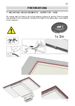
PREPARATIONS
7. MOUNTING REQUIREMENTS
-
KITCHEN FURNITURE AND WORKTOP
Safety instructions for the kitchen furniture fitter
Summary of Contents for NIVEL 8000 ML Series
Page 11: ...DE 11 Draufsicht Vorderansicht 5 ABMESSUNGEN ...
Page 12: ...DE 12 5 ABMESSUNGEN LÜFTEREINHEIT ...
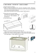
Page 18: ...DE 18 8 BEARBEITUNG ARBEITSPLATTE ...
Page 35: ...EN 35 top view front view 5 DIMENSIONS ...
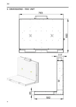
Page 36: ...EN 36 5 DIMENSIONS FAN UNIT ...
Page 59: ...FR 59 Vue du dessus Vue de face 5 DESSINS TECHNIQUES EN DIMENSIONS ...
Page 60: ...FR 60 5 DIMENSIONS UNITÉ DE VENTILATION ...
Page 83: ...IT 83 Vista dall alto Vista frontale 5 DIMENSIONI DISEGNI TECNICI ...
Page 84: ...IT 84 5 DIMENSIONI UNITÀ VENTILATORE ...
Page 107: ...ES 107 Vista en planta Vista frontal 5 DIMENSIONES ...
Page 108: ...ES 108 5 DIMENSIONES UNIDAD DE VENTILADOR ...
Page 131: ...NL 131 Bovenaanzicht Vooraanzicht 5 AFMETINGEN ...


