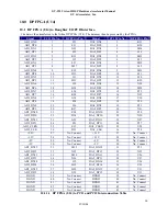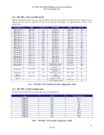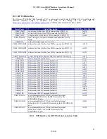
GV-395 Virtex-II DSP Hardware Accelerator Manual
GV & Associates, Inc.
07/10/04
8
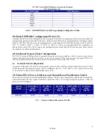
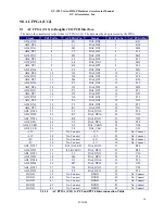
Slave Serial Signal
JP5 Connection
VCC 1
GND 2
CCLK 4
DONE 5
DIN 6
PROG 7
INIT 8
4.4.1.1
EEPROM Slave Serial Programming Configuration Table
5.0
Flash EEPROM Configuration FPGA (U1)
Normally, this FPGA will be configured by the serial prom (U3) which is programmed at the factory to perform the
configurations operations described in Section 4. However, this FPGA maybe reprogrammed by installing a jumper
block on JP4. The FPGA may now be reprogrammed by connecting the JTAG download cable to JP7 as follows:
VCC ->1, GND->2, TDO -> 3, TDI -> 4, TCK ->5, TMS ->6. This is not recommended but it would have no
adverse effects on the GVA-395 as long as the configuration pins for the other FPGAs are not used. Please refer to
the schematic for additional information.
6.0
On-Board System Clock Configuration
The GVA-395 uses an 50 MHz oscillator to generate the on-board system clock. which has a SG-615 form factor such as those
found in the Digi-Key catalog. The System clock is on pin AF18 for Virtex-II FPGAs and on pin 15 of the Spartan-II FPGAs. To
select the on-board oscillator as the system clock connect a jumper block between pins1 and 2 of JP8
6.1
External Clock Configuration
An exterior clock source (P1) may be selected as the system clock by installing a jumper block between pins 2 and 3
of JP8. Insure that this clock source meet the TTL minimum value (V
ih
= 2.4V and V
il
= 0.4V) and does not exceed
7V in reference to Ground before attaching the source to P1.
7.0
Xilinx FPGA Power-On Reset and Manual Reset Push Button Switch
The power-on reset may be used for initialization purposes. There is also a manual reset push button switch (SW1)
which will reactive the reset signal. It should be noted that if the +3.3V supply voltage drops below +3.00V the
power-on reset will trigger.
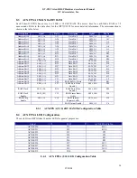
Signal
Name
ACX FPGA
(U10)
Pin No.
AC FPGA
(U12)
Pin No.
DP FPGA
(U14)
Pin No.
DPX FPGA
(U16)
Pin No.
E1 FPGA
(U18)
Pin No.
RESETL AG18 AG18 AG18 AG18 18
7.1.1
Power-on Reset Interconnect Table


