3. INSTALLATION
3.3 System Memory (DRAM )(J1, 4, 5, 7, 11, 13)
3.3.1
SIMM (Single Inline Memory Module) and DIMM (Dual Inline Memory
Module)
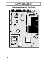
The SL5598 features four (4) 72-pin SIMM and two (2) 168-pin DIMM
sockets. The system memory size can be configured in a variety of ways by
using different combinations of the four 72-pin DRAM SIMM or two 168-pin
DIMM.
3.3.2 Installation Procedure
Step1:
Pin 1 of the SIMM must match pin 1 of the SIMM socket, same to the DIMM.
Step2:
Insert SIMM module into SIMM socket at a 45 degree angle. Push it ahead to
90 degree angle until it locks firmly into the SIMM socket.
Insert the DIMM module into the DIMM socket vertically. After inserting the
DIMM module completely into the socket, push up on the socket latches
securing the DIMM into place
If pin 1 of the DIMM module does not line up with pin 1 of the socket, the
DIMM module will not be inserted correctly into the socket. Same to SIMM.
Be careful not to misfit the DIMM Module into DIMM sockets in the wrong
SIMM1
SIMM2
SIMM3
SIMM4
DIMM1
DIMM2
C
SIMM
DIMM
Summary of Contents for SL5598
Page 5: ...EASY INSTALLATION...
Page 9: ...2 FEATURES Photo Of The Motherboard...
Page 35: ...3 INSTALLATION...


