48
GVM-VAC
www.gvm-vac.com
Service Section
5.1 Engine Electrical Troubleshooting Guide
ENGINE RUNS ONLY WHEN OVERRIDE BUTTON IS DE-
PRESSED
1. Make sure the PTO is disengaged.
2. Take a look at the limit switch located at the inspection door of
the blower housing. Check to be sure that the inspection door
closes completely and that the door presses in the limit switch.
The limit switch is extremely sensitive and only needs to open
1/64” to shut the engine off.
3. If the inspection door closes properly and presses in the limit
switch properly, then disconnect the two wires from the back of
the limit switch.
4. Start the engine using the normal procedure then release the shut
off button. If the engines continues to run then the problem lies
in the limit switch or the limit switch wiring. If the engine still
cuts off then the limit switch is not the cause, go to Testing the
shut off switch.
TO TEST THE LIMIT SWITCH:
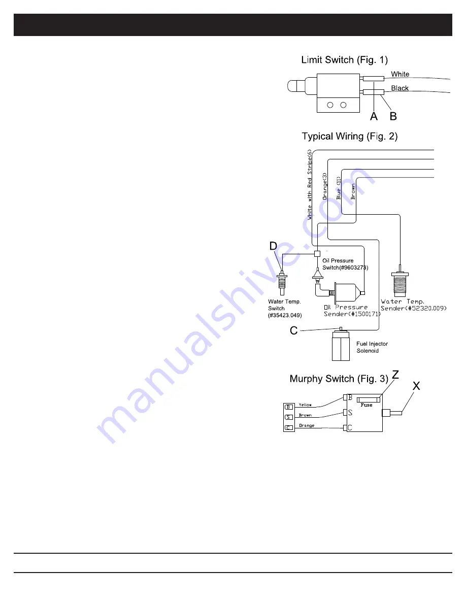
5. With an ohm meter check the resistance of the terminals A & B
(Fig. 1) while the button is not depressed. There should be no
resistance or continuity. With the button depressed there should
be full continuity or infinite resistance, if not the switch is bad
and should be replaced.
TESTING THE SHUT OFF (MURPHY) SWITCH:
6.
Turn the ignition switch to the first position.
7. Put a test light to terminal B (Fig. 3) to test for current. If there
is no current at B, power is not getting to the shut off switch.
Then the problem is not the shut off switch.
8. If there is current at terminal B, put a test light on the fuse at
location Z (Fig. 3). If there is no current there the fuse is blown.
Replace fuse.
9. If there is current at B and Z, push the override button (letter X,
Fig. 3) in on the shut off switch. While the button is depressed
place the test light on terminal C (Fig. 3). If there is current at
terminal C then the shut off switch is functioning properly and
the problem lies elsewhere. If there is no current at terminal C
then the shut off switch is defective and needs to be replaced.
10. Next locate the fuel solenoid valve located on the fuel injector
pump (Letter C, Fig. 2). It has an orange wire running to it. Pull the ignition switch to the first position. Put a test
light on the terminal of the fuel solenoid where the wire is attached. Test light should light up showing current, if
not shut off switch is bad. Replace.
11. If engine still cuts off after shut off button is released then test the water temperature switch (located on the engine
block, Letter D, fig. 2) by removing the brown wire attached to the temperature switch. Start the engine using
the normal procedure then release the shut off button. If the engine continues to run then the water temperature
switch is defective. Replace the switch. If the engine shuts off, do the same test on the oil pressure switch. If the
engine continues to shut off after this test call ODB for additional service procedures.
Summary of Contents for GVM8000
Page 67: ...67 GVM VAC www gvm vac com Service Section 5 10 7 Trailer Plug Wiring Diagram ...
Page 68: ...68 GVM VAC www gvm vac com Service Section 5 10 8 Trailer Wiring Diagram ...
Page 69: ...69 GVM VAC www gvm vac com Service Section 5 10 9 Brake Wiring Harness ...
Page 71: ...71 GVM VAC www gvm vac com Service Section 5 10 11 Remote Throttle Clutch Wiring Harness ...
Page 92: ...92 GVM VAC www gvm vac com 7 5 Kraft Fluid Drive Group Optional Fluid Drive Coupler Optional ...


