background image

K-BUS

KNX/EIB 3.5/5.0/10.1 inch Touch Panel Plus

6

R

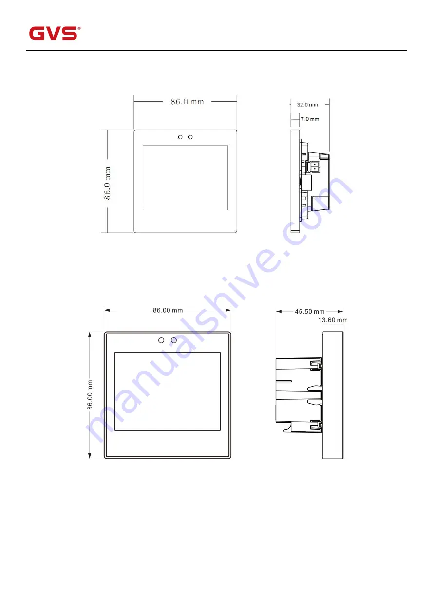
Chapter 3 Dimension and Wiring Diagram

3.1 Dimension

CHTF-3.5/20.1.2x

x=1,2,4, Slim

CHTF-3.5/20.2.2x

x=1,2,4, Classic

Summary of Contents for CHTF-10.1/20.1.2 Series

Page 1: ... CHTF 3 5 20 1 2x x 1 2 4 Slim CHTF 3 5 20 2 2x x 1 2 4 Classic CHTF 5 0 20 1 2x x 1 2 4 Slim CHTF 10 1 20 1 2x x 1 2 4 x 0 White 1 Black 2 Silver 3 Gray 4 Gold 5 Orange 6 Green 7 Blue 8 Yellow KNX EIB Home and Building Control System User Manual ...

Page 2: ...om strong magnetic field high temperature wet environment 2 Please do not fall the device to the ground or make them get hard impact 3 Please do not use wet cloth or volatile reagent to wipe the device 4 Please do not disassemble the devices ...

Page 3: ...tion 23 5 10 Setting page 25 Chapter 6 ETS Parameters Configuration 26 6 1 Parameter General 26 6 2 Parameter General sensor 30 6 3 Parameter Main page setting 32 6 4 Parameter Page function setting 34 6 5 Parameter Setting Window Controller General 61 6 6 Parameter Setting Window Time function setting 67 6 7 Parameter Setting Winsow Event Group setting 69 6 8 Parameter setting window Logic functi...

Page 4: ...sembly and programming details and explains how to use the Touch Panel by the application examples The Touch Panel is connected to the bus via the EIB connection terminals and need a 12 30V DC additional supply voltage It is available to assign the physical address and set the parameters by Engineering design tools ETS with knxprod higher than edition ETS4 The 3 5 5 0 10 1 inch Touch Panels use th...

Page 5: ... connection terminal black red Auxiliary power supply Pluggable screw terminal Operating and Indicating Red LED and Programming button For assignment of the physical address Green LED flashing Indicate the device running normally Temperature Operation 5 C 45 C Storage 25 C 55 C Transport 25 C 70 C Environment Humidity 93 except for dewing Installation Wall mounted installation first install the ir...

Page 6: ...B KNX Via bus connection terminal black red Auxiliary power supply EIB auxiliary power supply terminal yellow white Operating and Indicating Red LED and Programming button For assignment of the physical address Green LED flashing Indicate the device running normally Temperature Operation 5 C 45 C Storage 25 C 55 C Transport 25 C 70 C Environment Humidity 93 except for dewing Installation Wall moun...

Page 7: ...nal black red Auxiliary power supply Pluggable screw terminal Operating and Indicating Red LED and Programming button For assignment of the physical address Green LED flashing Indicate the device running normally Temperature Operation 5 C 45 C Storage 25 C 55 C Transport 25 C 70 C Environment Humidity 93 except for dewing Installation Wall mounted installation first install the iron bracket on the...

Page 8: ... Auxiliary power supply EIB auxiliary power supply terminal yellow white Operating and Indicating Red LED and Programming button For assignment of the physical address Green LED flashing Indicate the device running normally Temperature Operation 5 C 45 C Storage 25 C 55 C Transport 25 C 70 C Environment Humidity 93 except for dewing Installation Wall mounted installation first install the iron bra...

Page 9: ...K BUS KNX EIB 3 5 5 0 10 1 inch Touch Panel Plus 6 R Chapter 3 Dimension and Wiring Diagram 3 1 Dimension CHTF 3 5 20 1 2x x 1 2 4 Slim CHTF 3 5 20 2 2x x 1 2 4 Classic ...

Page 10: ...K BUS KNX EIB 3 5 5 0 10 1 inch Touch Panel Plus 7 R CHTF 5 0 20 1 2x x 1 2 4 Slim CHTF 10 1 20 1 2x x 1 2 4 ...

Page 11: ...ion terminal 4 KNX EIB bus connection terminals 5 The red LED indicates entry to the physical address programming state and the green LED flash indicates that the device application layer is working properly 6 Programming button 7 TF card slot 8 Micro USB socket 9 Display reset button This function is not currently supported It is a reserved function 10 Internal temperature sensor ...

Page 12: ...ower connection terminal KNX EIB bus connection terminals Connection block between application module and coupler Programming button The red LED indicates entry to the physical address programming state and the green LED flash indicates that the device application layer is working properly Internal temperature sensor Restart the device TF card slot ...

Page 13: ... display area Auxiliary supply connection terminal EIB KNX bus connection terminal Red LED for entering the physical address green LED for application process normally running Programming button TF card slot Micro USB socket Reset button reset screen display but not reset application Internal temperature sensor ...

Page 14: ...CHTF 10 1 20 1 2x x 1 2 4 Auxiliary power connection terminal Programming button EIB KNX bus connection terminal Red LED for entering the physical address green LED for application process normally running Micro USB socket System Reset button TF card slot ...

Page 15: ... control Switch shutters curtains and adjust louver angles Value sending function Values can be sent for different data types including scene calls and storage Display air quality test value AQI temperature humidity PM2 5 PM10 VOC and CO2 displays can be set and these values are detected by an external sensor Up to 4 items can be set in one interface HVAC control HVAC is mainly used to control the...

Page 16: ... switch mode air volume and so on The air conditioning gateway control is suitable for controlling for example a VRV air conditioning system and needs to be controlled with the KNX to VRV air conditioning gateway RGB dimming Mainly for dimming RGB LED lights using absolute dimming Floor heating control Two point control method is used to automatically switch the floor heating according to the temp...

Page 17: ... function page you can go through the upper right corner Icon return to homepage Right corner Icon is the temperature that detected by the sensor inside the product Icon is the connection status for the KNX bus 5 2 General Function Page Figure5 2_1 5 2 1 Switch Control When the corresponding icon on the touch panel is on the device sends a message with the Switch value of 1 When the corresponding ...

Page 18: ... of 0 2 Click icon the device sends a packet with a luminance target value of 100 3 Click icon return to the function page Status Feedback The on and off status of the icon is used to feedback the status of the light On indicates that the brightness value of the light is greater than 0 and off means the brightness value of the light is 0 The value of the slider shown in Fig 5 2_2 is the luminance ...

Page 19: ...uch icon The device sends a message with an Open Close value of 0 This feature has no status feedback Curtain with 2 sliders Move Adj Percent Figure 5 2_4 The curtain icon on the touch function page pops up as shown in Figure 5 2_4 The first slider is stroke control and the second slider is angle control 1 Slide the first slider and the device will send a message with the corresponding Shutter pos...

Page 20: ...con The device sends a message with a target value of 100 3 Click icon You can return to the function page 4 The status display of the slider can be updated via the bus over the status of the position Position status 5 3 Air Quality Feature Page Figure 5 3_1 The air quality feature page displays seven parameters which are AQI Temperature Humidity PM2 5 PM10 CO2 VOC Note Only four of these paramete...

Page 21: ... to the object Humidity via the bus Heating cooling status For heating cooling mode switching when the database HVAC control mode is set to Heating and Cooling the heating cooling mode can be switched by touch message Wind speed Touch this icon and the wind speed will switch from OFF to AUTO OFF in the current wind speed range When switching to the wind speed OFF 1 2 and 3 the switching takes effe...

Page 22: ...n the protection mode and the relative change in the temperature adjustment of other modes can be applied to the setting temperature of all modes except the protection mode In the case of an absolutely set temperature this set temperature adjustment acts only on the current mode 5 5 AC Feature page Figure 5 5_1 On off button Used to turn on off 1 is gray after power on and 1 is bright after shut d...

Page 23: ...ed level In the Gateway Integrate control mode the boot wind speed does not change in the IR Split Unit control mode the boot displays the corresponding wind speed profile according to the configuration Temperature display Touch or icons the display can be switched between the room temperature and the outdoor temperature Units can be selected based on the configuration of the database Temperature ...

Page 24: ... Play source For playing source selection touch this icon will pop up the interface as shown in Figure 5 6_2 USB SD AUX FM can be selected Touch icon you can return to the function page Status updates can be made through objects Figure 5 6_2 Previous Next The touch icon can select the previous song or the next song Play Pause Touch icons play or pause songs Status updates can be made through objec...

Page 25: ...ower on 1 is bright and is gray after power off In the off state except the status of the ON OFF and the room temperature that can be updated through the bus the rest of the icon states cannot be updated through the bus or manually controlled Room Temperature According to the parameter setting of database on ETS the display unit is configured by Temperature display units you can select to display ...

Page 26: ...0 C by default it can be modified by the parameter Min Max set temperature 5 40 C According to the parameter setting of database on ETS you can select to display either Celsius C or Fahrenheit F 5 9 Ventilation Figure 5 9_1 ON OFF BUTTON It is used to turn on off Ventilation the initial state when powered up is based on the database definition is gray after power on is bright and is gray after pow...

Page 27: ...ife value Touching this icon will pop up the interface as shown in Figure 5 9 2 Figure 5 9_2 Selecting will reset the filter life value to 100 Selecting to return to the function page The lifetime value of the filter can be modified by the object Wind Speed Touch this icon the wind speed will be switched from the current wind speed level by 1 AUTO 1 cycle When switching to wind speeds 1 2 and 3 sw...

Page 28: ...hown in Figure 5 10_1 and then click the icon to enter the page shown in Figure 5 10_2 Time setup Click the icon to enter the time setup page as shown in Figure 5 10_3 Set the current time via swiping operation then click icon to save and icon is not saved Version view Click the icon to enter the software version viewing page as shown in Figure 5 10_4 you can view the current software and MCU vers...

Page 29: ...ing is mainly used to set the general settings of the touch panel such as time screen saver whether the prompt tone is turned on during operation etc Parameter Interface Language To set the language of Touch Panel Options Chinese Polish English Russian German Turkish Italian Spanish French Greek Dutch Other Note The 3 5 5 0 10 1 inch Touch Panel supports Chinese and English only temporally ...

Page 30: ... is inactive In order to reduce the bus load as much as possible the maximum time interval should be selected according to actual needs Parameter Date and Time can be changed via bus To set whether the display date time on the screen can be modified via the bus Options NO YES If YES is selected the object Date and the object Time are visible and the date and time can be modified by the two objects...

Page 31: ...ion detected under the function page Available Options 0 255s NOTE The 3 5 5 0 10 1 inch Touch Panel doesn t support this function temporally Parameter Screen saver To set whether to enable the screen saver function of the touch panel Options Disable Clock Album If you select Clock the screen shows the clock when the panel enters to screen saver mode If Album is selected after entering the screen ...

Page 32: ... page After being enabled when the device starts up or the bus is powered on again it will send telegram to the bus to read the value of temperature humidity CO2 PM2 5 etc detected by the sensor After being enabled when the device starts up or the bus is powered on again it will send telegram to the bus to read brightness value status of switching or dimming After being enabled when the device sta...

Page 33: ...function temporally The following three parameters are used for correction value and sending setting of the screen s built in temperature sensor If other functions choose internal sensors as well please refer to the settings here Parameter Internal sensor calibration Options 5 0 5 This parameter is to set the temperature correction value of the built in temperature sensor that is to modify the mea...

Page 34: ...measurement value of the external sensor the temperature will be displayed as 0 or the value detected by the built in temp sensor Parameter When external sensor fault Internal sensor display This parameter is visible when the external temperature sensor is selected Options NO YES NO When the external sensor is in fault and the internal sensor display is not enabled 0 will be displayed by default Y...

Page 35: ...rnal sensors to measure temperature it is recommended to turn off the backlight time set to 5 15s otherwise the measurement of the temperature error is large 6 3 Parameter Main page setting Figure 6 3_1 Parameter Main page setting settings interface Used to set the layout and page navigation features of the home page you can set up to 9 pages of navigation depending on the product type The paramet...

Page 36: ... applicable device type such as 2x4 3 5 5 0_h 10 1 inch layout 2 lines 4 column can decorate up to 8 navigation page function apply to 3 5 inch screen 5 0 inch horizontal screen Parameter Navigation function x x 1 9 Sets whether to enable navigation function x Available options Disable Enable When Enable the following parameters are visible Parameter Navigation page Sets the function page that the...

Page 37: ...r Page function setting Page function setting show in Figure 6 4 1 is used to set whether the page is functional Figure 6 4_1 Parameter Page function setting setting interface Parameter Function page x x 1 10 Set whether to enable the function of page x Available options Disable Enable When Enable Parameter interface Page x is visible as shown in Figure 6 4_2 this interface can set the function of...

Page 38: ...r Page x Lighting Curtain Value send Parameter Page x setting interface as shown in Figure 6 4_2 is used to set pages functionality Figure 6 4_2 Parameter Lighting Curtain Value send setting interface Figure 6 4_2 Parameter Lighting Curtain Value send setting interface ...

Page 39: ...ollowing sections describe the parameter settings for each feature The page features in this section are mainly about lighting curtains and parameter settings for sending values as follows Parameter Page Layout Sets the layout of the feature page Available options 1X1 3 5 5 0 10 1 inch 1X2 3 5 5 0_H 10 1 inch 1X3 3 5 5 0_H 10 1 inch 2X2 3 5 5 0 10 1 inch 2X3 3 5 inch 2X4 3 5 5 0_H 10 1 inch 2X1 5 ...

Page 40: ...con x Sets the function of the icon x Available options Switch Switch Dimming Value send Curtain with 3 Buttons Open close stop Curtain with 1 Slider Move Percent Curtain with 2 sliders Move Adj Percent Switch The icon is used to control the switch Object switch and object switch status are visible and these two objects are typically used in conjunction For example switch corresponds to the switch...

Page 41: ...nt Apply to Venetian blinds control with two slider adjust the curtain position and Venetian angle in percentage form The following parameters are visible when you select a value to send feature Parameter Datatype of object This sets the type of object that sends the value Available options 1bit On Off 2bit 0 3 4bit 0 15 1byte 0 255 1byte 0 100 1byte scene control 2byte 32768 32767 2byte 0 65535 P...

Page 42: ...re 6 4_3 Parameter Air Quality display setting interface Parameter Items x x 1 4 function in List display Sets the contents of each item to display up to 4 items Available options Disable AQI Temperature Humidity PM2 5 PM10 CO2 VOC These values are detected by an external sensor and passed to the screen for display To enable the display the screen will appear empty if the detected values are not r...

Page 43: ...troller also need to refer to the controller general parameter setting interface Figure 6 4_4 Parameter HVAC setting interface Parameter Temperature reference from This parameter sets the source of the HVAC function temperature reference Available options Internal sensor External sensor When selecting the reference internal sensor the temperature is determined by the setting of the built in sensor...

Page 44: ...request is sent to the external temperature sensor Parameter Object type of fan speed This parameter is used to set the data type of wind speed Available options 1bit 1byte Output value for fan speed Parameter Output value for fan speed low medium high These three parameters are visible when the wind speed object type is 1byte and define the values that are sent to each wind speed Options 0 255 St...

Page 45: ...protection mode The screen will update to the corresponding mode according to the received telegram value Parameter Type of heating cooling control To set the control type of heating cooling function Different control types are used to control different thermostats Options Switching on off use 2 point control Switching PWM use PI control Continuous control use PI control Parameter Controller setti...

Page 46: ...rameter setting interface Gateway Integrate _1bit Figure 6 4_5 Air conditioner parameter setting interface Gateway Integrate _1byte It is used to set AC control of two types of air conditioning IR Split Unit and Gateway Integrate The gateway integrate has two types of objects 1 bit and 1 byte IR air conditioning is controlled by 1byte object ...

Page 47: ...are visible when the air conditioning mode object type is 1byte to set the status feedback value of each mode Parameter Status value for Heat Cool Dry Fan These parameters are used to set the status feedback value of each mode and the touch panel will update the icon status of the mode according to the received feedback value Available Options 0 255 Parameter Date type of fan speed This parameter ...

Page 48: ...tpoint Options 1byte real emperature value 2byte knx standard DPT Parameter Min Man set temperature 16 32 These two parameters are used to limit the adjustable range of the temperature setpoint The minimum value must be lower than the maximum value If the temperature setting value exceeds the limit range it will be output as the limit value Split Infrared IR air conditioner Figure 6 4_6 Air condit...

Page 49: ... default temperature the temperature at this time is also limited to the maximum minimum value The following three parameters is to set the initial icon status displayed on the touch panel when power on Parameter Default mode for power on To set initial mode displayed on the touch panel when power on Options Heating Cooling Dry Fan Parameter Default setpoint for power on To set initial temperature...

Page 50: ...on is enabled the object used to control the music playback will be visible Such as on off play stop volume control previous next play mode audio source etc the background music module can be controlled directly through these objects Parameter Power object telegram define Parameter Play pause object telegram define Parameter Song select object telegram define Parameter Volume object telegram defin...

Page 51: ...ack value of the random play mode the screen will update the icon status according to the received feedback value Available Options 0 255 Parameter Status value for playlist cycle It is to set the status feedback value of the playlist cycle play mode The screen will update the icon status according to the received feedback value Available Options 0 255 Parameter Status value for play in order It i...

Page 52: ...GB RGBW RGB Suitable for adjusting RGB tricolor lamps RGBW Suitable for adjusting RGBW four color lights Note The 3 5 5 0 10 1 inch touch panel supports RGB types only temporally Parameter object type It is used to set the object type Options Suitable for RGB types 1x3byte 3x1byte Suitable for RGBW type 1x6byte 4x1byte 1x3byte RGB dimming via a 3byte object 3x1byte RGB dimming with three 1 byte ob...

Page 53: ...n Figure 6 4_9 Figure 6 4_9 Floor heating parameter setting interface Parameter Temperature reference from This parameter sets the source of the referential temperature of floor heating function Options Internal sensor External sensor Note The floor heating temperature setting parameter is similar to the HVAC function Please refer to section 6 4 3 for details ...

Page 54: ...0 Heat on 0 Heat off 1 Parameter Temperature control method The temperature control is via 2 Point Control While the real temperature is higher than Setting Value the heating is Off while below the setting value the heating is On Parameter Hysteresis 0 200 0 1 This parameter is used to set the hysteresis of Set Value Options 0 100 While the real temperature is higher than setting temperature the h...

Page 55: ...o Disable 0 Enable 1 Disable 1 Enable 0 While the last two options are selected the object used to disable enable the timing function is visible It can disable enable the Heating Timer function through object After completed program or bus recovery the default statue is Disable Switching on off or choosing the scene can exit the timer Parameter Timer x x 1 8 This parameter is used to enable Timer ...

Page 56: ...day at hours h at minutes min This parameter is used to set the Time Point of Timer x It will execute the timer x while the time is up Options Weekday Monday Tuesday Wednesday Thursday Friday Saturday Sunday Monday Friday Saturday Sunday Monday Sunday Hours h 0 23 Minutes min 0 59 ...

Page 57: ... which is mainly to set the parameter of ventilation system Figure 6 4_10 Ventilation system parameter setting window Parameter Temperature reference from This parameter is used to set temperature reference from for floor heating Options Internal sensor External sensor NOTE The parameter setting of Radiant Floor Heating is similar to HVAC please refer to Section 6 4 3 ...

Page 58: ...d while the ventilation is turn on Options Low Medium High Parameter Data type of Fan speed This parameter is used to set the data type of Fan speed Options 1bit 1byte Parameter Output value for fan speed off low medium high It is visible while the data type of Fan speed is 1 byte defining the output value of fan speed off low medium high Options 0 255 Parameter Object value for fan speed off low ...

Page 59: ...very function This parameter is used to set whether to enable Heat recovery function Options No Disable 0 Enable 1 Disable 1 Enable 0 If the last two options are selected the Heat Recovery is enabled by default that is it is enable once boots While No is selected the heat recovery is not controllable Parameter Filter timer counter This parameter is used to set whether to enable the filter timer co...

Page 60: ...e Fan level of scene x Options Off Low Medium High Parameter Heat Recovery This parameter is used to set the Heat recovery of Scene x Options Off On This parameter is invalid when the heat recovery is disabled Px Auto Control After the Auto Control is activated the ventilation system will automatically adjust the Fan level according to the control value The following parameters are visible when th...

Page 61: ...am value 1 When receiving 0 the Auto Operation exit After bus voltage recovery or reset Auto Operation is not activated by default Parameter Control value reference from This parameter is used to set the Control value reference from of Auto Operation Options PM2 5 ug m3 CO2 ppm Parameter Period for request control value 0 255 1min This parameter is used to set the period for request control value ...

Page 62: ...ual to the setting threshold value the high range fan lever is run Options 1 999 1 4000 Tip The controller evaluates the threshold in ascending order First check OFF low fan speed threshold low fan speed medium fan speed medium fan speed high fan speed The correctness of function execution is guaranteed only in this situation Parameter Hysteresis value is threshold value in 10 30 100 400 This para...

Page 63: ... s high fan speed will change at a control value of 50 75 25 and the new fan speed will be low fan speed because 50 is between 35 and 55 irrespective of hysteresis so the fan speed is ignored For example 2 Take PM2 5 as an example OFF the threshold value of fan speed 1 is 20 Fan speed 1 the threshold of fan speed 2 is 40 Speed 2 Speed 3 the threshold value is 70 Delay value is 10 When fan speed is...

Page 64: ...the auto mode The minimum running time should be taken into consideration at every fan speed including off under the auto mode For example when the current speed is at low while the target speed is high the speed will be increasing gradually from low to medium and then finally to high And the speed will be switched only after the minimum time is over The delay time for speed switching should also ...

Page 65: ...K BUS KNX EIB 3 5 5 0 10 1 inch Touch Panel Plus 62 R Fig 6 5_1 Controller General parameter setting window ...

Page 66: ...fter restart This parameter is used to set the operation mode when the device is rebooted Options Standby mode Comfort mode Night mode Frost heat protection Parameter Extended comfort mode 0 255 0 inactive min This parameter is used to set the delay time of the confirm mode Options 0 1 255 min 1 When the setting value is 0 the comfort mode is disabled 2 When the setting value is from 1 255 and the...

Page 67: ...ed based on the defined basic temperature setpoint Absolute Each mode have it s own temperature Setpoint Enable Relative the following parameters are available which are used to set the temperature setpoint under Relative operation mode Parameter Basic setpoint temperature This parameter is used to set the basic temperature value The setpoint temperature for the comfort mode is generated based on ...

Page 68: ...telegram to the bus to active the relevant heating actuator to avoid low temperature in the room Parameter Actual Temp threshold in heat protection 30 40 for cooling This parameter is used to set cooling function temperature setpoint under heat protection mode Options 30 40 When the room temperature is higher than the set value here the controller will send a control telegram to the bus to active ...

Page 69: ...Hysteresis 0 200 0 1 For heating Parameter Upper Hysteresis 0 200 0 1 For cooling The parameter is used to set the delay value of the HVAC heating or cooling Options 0 200 Under heating status when the actual temperature T setpoint temperature stop heating When the actual temperature setpoint temperature Delay value start to heat For example when the delay is 3 setpoint temperature is 22 T is high...

Page 70: ...tting parameter setting window is shown in Fig 6 6_1 it can enable at most 8 time function Time funcation x x 1 8 parameter setting window is shown as the Fig 6 6_2 it is used to set the timing and output value of every Timing etc Every Time function parameter is the same so we just take one of them for example to explain everything setting Fig 6 6_2 Time function x parameter Setting Window ...

Page 71: ... to set the Time x name it support maximum 12 characters 6 Chinese characters Parameter Disable function This parameter is used to set whether to set the disable object or enable the time function The Options No Yes If choose yes the default setting is enable Parameter Trigger value of disable object This parameter is used to set the trigger value of disable enable Disable 1 enable 0 Disable 0 ena...

Page 72: ...sable enable parameter setting window Fig 6 7_2 G x Output y Function parameter setting window Parameter Event Group x Function x 1 4 This parameter is used to enable the event group The options Disable Enable The 8 output is available when the certain group is enabled As the function of each 4 groups and each 8 output is the same so we just take one of them for example to explain everything setti...

Page 73: ...1s This parameter is used to set the delay time for sending to the bus The options 0 255 6 8 Parameter setting window Logic function setting Logic function parameter setting window is shown in Fig 6 8_1 it is used to enable the Logic function and at most 8 logic functions can be used Fig 6 8_1 Logic function disable enable parameter setting window Parameter Function of channel This parameter is us...

Page 74: ...ameter Input a b c d e f g h This parameter is used to set whether and in which way the logic input x is involved in the operation The Options Disconnected Normal Inverted Disconnected Not involved in the operation Normal Involved in the operation directly Inverted Involved in the operation with inverted input Note the initial value will not be inverted ...

Page 75: ...ameter Output send when This parameter is used to set the condition of sending the logic operation result Receiving a new telegram Every change of output object Receiving a new telegram when a new logic input value is received the logic operation result will always be sent to the bus Every change of output object when the logic operation result changes it will be sent to the bus Note Although the ...

Page 76: ...tup 1 64 0 inactive This parameter is used to set the default activated Scene No Of the logic Gate after device startup This scene should be configured in the relevant parameter The options 1 64 0 inactive Parameter z Gate trigger scene NO is 1 64 0 inactive z 1 8 This parameter is used to set the gate triggered scene No Each logic can support Maximum 8 scenes The options 1 64 0 inactive Parameter...

Page 77: ...ameter setting window Parameter Threshold value data byte This parameter is used to set the threshold value data type The options are 4bit 1byte 2byte 4byte Parameter Threshold value This parameter is used to set the threshold value The range is determined by the data type 4bit 0 15 1byte 0 255 2byte 0 65535 4byte 0 4294967295 Parameter If Object value Threshold value Parameter If Object value Thr...

Page 78: ...the object is equals to the threshold value the logic operation result 1 will be sent to the bus Parameter Output send when This parameter is used to set the condition of sending the logic operation result The options Receiving a new telegram Every change of output object Receiving a new telegram when a new logic input value is received the logic operation result will always be sent to the bus Eve...

Page 79: ...2x2byte 1x3byte 3x1byte 3x1byte 1x3byte Parameter Output send when This parameter is used to set the condition of sending the logic operation result The options Receiving a new telegram Every change of output object Receiving a new telegram when a new logic input value is received the logic operation result will always be sent to the bus Every change of output object when the logic operation resul...

Page 80: ...unication object is used to modify show date in TFT system via receiving a telegram with date 2 Time General 3Byte C W 10 001 time of day The communication object is used to modify show time in TFT system via receiving a telegram with time 3 Screen backlight brightness General 1byte C W 5 001 percentage The communication object is used to modify the brightness of the panel The brightness output ra...

Page 81: ...ceive the PM2 5 value from the bus and update it to the panel Unit is ug m3 The value ranges 0 999ug m3 Note Currently the object is reserved 369 PM10 External sensor 2byte C W T U 7 001 pulses The communication object is used to receive the PM10 value from the bus and update it to the panel Unit is ug m3 The value ranges 0 999ug m3 Note Currently the object is reserved 370 Humidity External senso...

Page 82: ...a Type Flags DPT 5 9 Switch Page x Icon y 1bit C T 1 001 switch The communication object is used to send out an ON telegram or an OFF telegram to the bus to turn on or off lighting Telegram value 1 ON 0 OFF 7 Switch Status Page x Icon y 1bit C W T U 1 001 switch The communication object is used to receive a telegram with on off status response from dimmer or other bus device and in the TFT system ...

Page 83: ...Obj 9 The communication object is used to send messages of controlling curtain position to the BUS Message 0 100 Obj 11 The communication object is used to receive response from curtain controller about the position status of curtain Message 0 100 13 Shutter position Page x Icon y 1byte C T 5 001 percentage 14 Slat position Page x Icon y 1byte C T 5 001 percentage 15 Position status Page x Icon y ...

Page 84: ...tch control 3 007 dimming control 5 010 counter pulses 5 001 percentage 18 001 scene control 8 001 pulses difference 7 001 pulses The communication object is used to send input value of object When distinguishing long press short press only object input value of short press operation will be transmit The range of numerical value is decided by data type Different data type of communication object w...

Page 85: ...ge x Air Quality 2Byte C W T U 9 001 temperature The communication object is used to receive temperature measurement value sent by the temperature sensor from the BUS Range 40 40 9 Humidity Page x Air Quality 2byte C W T U 9 007 humidity The communication object is used to receive humidity measurement value sent by the humidity sensor from the BUS Range 0 100 10 VOC Page x Air Quality 2byte C W T ...

Page 86: ...put 2byte C W T U 9 001 temperature The communication object is used to receive temperature measurement value sent by the temperature sensor from the BUS Range 50 99 8 7 Setpoint adjustment Page x HVAC Input 2byte C W 9 001 temperature When the set temperature is opposite adjustment the adjustment of set temperature is only applied for the mode itself under protection mode Opposite changes of temp...

Page 87: ...nding mode will be activated and the mode display status will also update to relative mode on the panel When it s 1byte the relation between input value and operation mode is as following no 0 unused 1 Comfort mode 2 Standby mode 3 Night mode 4 Protection mode 5 255 Unused 13 Fan speed Fan speed low Page x HVAC Input 1byte 1bit C W T U 5 010 counter pulses 1 001 switch 14 Fan speed medium Page x H...

Page 88: ...rolling value of heating or cooling function to control the switch of HVAC valve and adjust internal temperature Sending message value switch on off with 2 point control on off Sending message value switch PWM with PI control on off Sending message value continuous control with PI control 0 100 25 Fan speed Fan speed low Page x HVAC output 1byte 1bit C T 5 010 counter pulses 1 001 switch 26 Fan sp...

Page 89: ...IR Split unit command The communication object is visible in split infrared mode which is used to send messages of air conditioner control The parameter can set controlling telegram 1 64 while the actual message value on the BUS is corresponding to 0 63 6 Status of Power Page x AC 1bit C W T U 1 001 switch The communication object is visible in VRV air conditioner mode which is used to receive fee...

Page 90: ... wind speed 1bit The communication object will be visible when it s in VRV AC mode the mode type of wind speed is 1bit which is used to send controlling message of wind speed automatic which can also receive status feedback 12 Status of Fan speed Page x AC 1byte C W T U 5 010 counter pulses 12 Fan speed low Page x AC 1bit C W T U 1 001 switch 1byte The communication object will be visible when it ...

Page 91: ... music on off as well as receiving status feedback of background music on off from the BUS Message value 1 On 0 Off 6 Play Pause Page x BgMusic 1bit C W T U 1 010 start stop The communication object is used to play pause music from background music module as well as receiving status feedback Message value 1 Play music 0 Pause music 7 Next song Previous song Page x BgMusic 1bit C T 1 007 step The c...

Page 92: ...x RGB Dimming 1byte C T 5 001 percentage The communication object is used to send brightness value of controlling R red channel to the BUS Message Value 0 100 6 Green dimming value Page x RGB Dimming 1byte C T 5 001 percentage The communication object is used to send brightness value of controlling G green channel to the BUS Message Value 0 100 7 Blue dimming value Page x RGB Dimming 1byte C T 5 0...

Page 93: ... object No Function Communication object name Type Attribute DPT 5 Heating on off Page x Floor heating 1bit C W T U 1 001 switch This communication object is used to send floor heating control commands It can also receive floor heating feedback status feedback The switch status corresponding to the packet value is specifically set by parameters 6 Setpoint Page x Floor heating 2byte C W T U 9 001 t...

Page 94: ...ject is visible when the wind speed type is 1byte and is used to receive the status feedback of wind speed The specific message value corresponding to each wind speed is defined by parameters 8 Fan speed Out Page x Ventilation 1byte C T 5 010 counter pulses The communication object is visible when the wind speed type is 1byte and is used to send a message controlling the wind speed to the bus The ...

Page 95: ...control value of the automatic operation is CO2 then under automatic conditions the fresh air system can be set to automatically adjust the wind speed according to the CO2 concentration 15 PM2 5 In Page x Ventilation 2byte C W T U The communication object is used to receive the input of the PM2 5 value and obtain the corresponding value from the bus to update the display The unit is ug m3 Range 0 ...

Page 96: ...bit C W 1 003 enable This communication object is used to disable enable the timing x function The disabled enabled message values are specifically defined by parameters After forbidden timing will not be enabled Form 7 4_1 Time function Communication Object Form 7 5 Event Group Communication Object Figure 7 5_1 Event Group Communication Object No Function Communication Object Name Type Attribute ...

Page 97: ..._2 Logic function_Gate forwarding communication object No Function Communication object name Type Attribute DPT 423 Gate value select 1st 8th Logic 1byte C W 17 001 scene number This communication object is used to select the logic gate forwarding scenario 424 427 Input x 1st 8th Logic 1bit 4bit 1byte C W 1 001 switch 3 007 DPT_Dimming control 5 010 DPT_counter pulses This communication object is ...

Page 98: ...mmunication object is used to send logical operation results That is the value that should be sent after the object input threshold is compared with the parameter setting threshold Form 7 6_3 Logic function_Threshold comparator Communication Object Form 7 6 4 Communication Object for Format convert 2x1bit 1x2bit function converts 2 1bit values into a 2bit value eg Input bit1 1 bit0 0 Output 2bit 2...

Page 99: ...it4 0 Bit5 0 bit6 1 bit7 1 1x2byte 2x1byte function converts a 2 byte value into two 1 byte values such as Input 2byte 55500 D8 CC Output 1byte low 204 CC Output 1byte high 216 D8 1x4byte 2x2byte function converts a 4 byte value into two 2 byte values such as Input 4byte 78009500 04 A6 54 9C Output 2byte low 21660 54 9C Output 2byte high 1190 04 A6 1x3byte 3x1byte function converts a 3byte value i...

Page 100: ...ol 5 010 DPT_counter pulses 7 001 DPT_pulses 232 600 RGB value 3x 0 255 12 001 DPT_counter pulses This communication object is used to output the converted value Form 7 6_4 Logic function_Format convert Communication Object Form Chapter 8 Appendix 8 1 Homepage icon list Multi function AQI HVAC AC MUSIC RGB Floor heat Ventilation Default Default Default Default Default Default Default Default Mult ...

Page 101: ...ault two states 1 Default Default Default Default Default Dimmer 1 Dimmer 2 Dimmer 3 Switch 1 Switch 2 Curtain 1 1 two states 2 two states 3 two states 4 two states 5 two states 6 Curtain 2 Curtain 3 Blinds Shutter Coffee Night 7 8 9 10 11 12 LeaveHome GoHome Game Cheers Dinner Read 13 14 15 16 17 18 Relax Music 19 20 Note 1 6 icons have two states that on and off display ...

Reviews: