EXTERNAL CONTROL
167
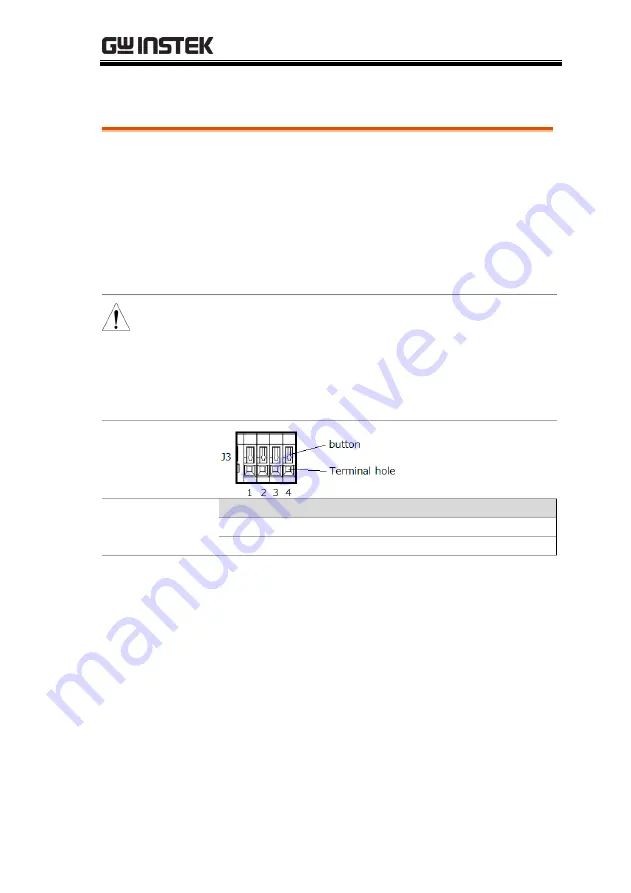
J3 port (PEL-3021H/PEL-3041H/PEL-3111H)
Description
Use wire of 24 to 28 AWG to connect with J3 port.
Please peel the coating of a wire approximately
10mm and then insert the wire to the terminal
hole while pushing the button on the terminal
hole of the J3.
To view the contact pin assignment of the J3,
please see page 219 in the appendix chapter.
WARNING Please insert the wire to the hole of terminal J3
deeply. A conductor part of the wire, please do not
come in contact with the frame and conductor part of
other wire.
To prevent electric shock, ensure the cover for the J3.
Pin Assignment
J3 Pin assignment
No Name
No Name
1 I MON OUT
2 V MON OUT
3 A COM
4 A COM
Summary of Contents for PEL-3000 Series
Page 1: ...DC Electronic Load PEL 3000 H Series USER MANUAL VERSION 2 00 ISO 9001 CERTIFIED MANUFACTURER ...
Page 24: ...PEL 3000 H User Manual 22 PEL 3111H PEL 3211 Booster Pack PEL 3211H Booster Pack ...
Page 41: ...GETTING STARTED 39 Fasteners 2 ...
Page 207: ...REMOTE CONTROL 205 6 7 8 9 The function check is complete ...
Page 229: ...APPENDIX 227 Operating Area PEL 3021 ...
Page 230: ...PEL 3000 H User Manual 228 PEL 3041 ...
Page 231: ...APPENDIX 229 PEL 3111 ...
Page 232: ...PEL 3000 H User Manual 230 PEL 3211 Booster Pack PEL 3021H ...
Page 233: ...APPENDIX 231 PEL 3041H ...
Page 234: ...PEL 3000 H User Manual 232 PEL 3111H PEL 3211H Booster Pack ...
Page 235: ...APPENDIX 233 ...


