background image


2

.

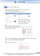
The function of Combining and Breaking up (The  function of Grouping and 

Ungrouping)

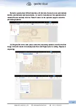
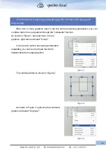
     When two or more graphics need to set the same processing parameters, you can 
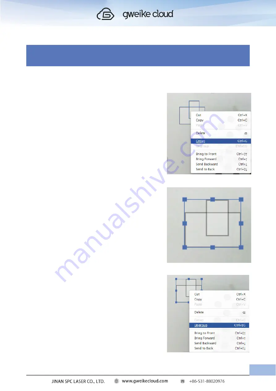
combine them into one graphics through the "composite" function.
As shown in Figure 1, box select two or more 
graphics, right-click and select "Group":

        If you need to set the processing parameters 
separately, you can use the break function to 
disassemble the merged graphics.

        The combined effect is shown in Figure 2:

        As shown in Figure 3, right-click the combined 
graphic and select "Ungroup":

(figure 1)

(figure 2)

(figure 3)

32

Summary of Contents for Desktop 3D Laser Printer

Page 1: ......

Page 2: ...aser in an environment free of flammable materials children pets spectators etc Always use Infrared Eye Protection Goggles when operating this laser Failure to due so may result in Permanent Blindness...

Page 3: ...uction 1 Function of extraction 2 The function of Combining and Breaking up The function of Grouping and Ungrouping 3 The function of Layer 4 Add option 5 The Function Of Copy 6 3D Engraving 7 The Fun...

Page 4: ...age taken by the camera has a large deviation from the actual cutting image the deviation within 2mm is normal 7 If the cutting material is larger than the machine format how to realize the front and...

Page 5: ...f the embedded laser is fully contained The laser cabinet has safety interlocks that turn the laser off if any access door is opened during operation and no special precautions are necessary to operat...

Page 6: ...regulations for laser and laser system manufacturers and for the Occupational Safety and Health Administration OSHA laser safety guidelines It contains detailed information concerning proper installa...

Page 7: ...Regulatory Compliance Gweikecloud has incorporated specific safety features into the Model 16000 Laser System in order to meet the requirements of 21 CFR 1040 and the International Standard IEC 60825...

Page 8: ...front one at the top One on the left and one on the right Laser radiation warning label this label is located at the back right side of the machine Laser Aperture Label This label is located on the l...

Page 9: ...e panel at the right side of the machine s cabinet Aperture Safety Label This label is located above the aperture inside the cabinet where laser beams enter the machine s engraving Area one on the lef...

Page 10: ...ure that problems do not occur 2 Do Not Operate Machine While Unattended Never operate your machine without someone watching the system There is a significant risk of fire if the machine is set improp...

Page 11: ...the laser system 2 Choose where to locate the system 3 Connect the exhaust system to your laser 4 Connect the electrical power 5 Register your system at www gweikecloud com Getting Acquainted Here s...

Page 12: ...eive two packages Package 1 includes GWEIKE Cloud laser printer material package and accessories Package 2 includes air filter Gweike Cloud Duct fan Duct adapter User Manuel 1 Certificate of conformit...

Page 13: ...n cover The box is specially designed to protect your gweikecloud through all shipments domestic and international Be sure to keep the box and packing materials as you ll need them if you want to tran...

Page 14: ...mb board and the sponge on the top of the box 3 Choose a table with a hard flat and stable surface If the desktop is unstable uneven or too small it may cause deviations of printing accuracy and may e...

Page 15: ...e the 3D laser printer out of the wooden box Remove the orange belt and the plastic bay belt Place it on the prepared desktop Open the cover of the machine and take out the accessories inside the mach...

Page 16: ...2 Machine installation 1 Pull out the waste scrap tray put the honeycomb board into the bottom of the laser printer and then reinstall the waste scrap tray 12...

Page 17: ...Don t put in honey comb plate from top side 2 Duct Fan Installation Manual Before Preparation Fan Screwdriver 120mm air hose 1 150mm air hose 1 120 150 reducer 1 13...

Page 18: ...r inlet of the fan 2 Unfold and stretch the retractable aluminum air hose 3 Connect one end of the 120mm air hose to the exhaust port of the machine and the othver end to the air inlet of the fan and...

Page 19: ...he 150mm air hose to the exhaust port of the fan and tighten the clamp with a screwdriver 5 Place the connected fan on the window sill with the air outlet facing outwards 6 Plug the power cord to fini...

Page 20: ...will be stable after the increase of cutting time then no smoke and dust will be discharged around the machine body Operation Note When operating gweikecloud make sure there are no USB cables and netw...

Page 21: ...te one now Register an operating account on the cloud laser Website Note If account already registered when make payment please use it and please don t register again Note If account already registere...

Page 22: ...18...

Page 23: ...click the to https www gweikecloud com cloud Login in your account Enter your account and password 5 Input your machine ID the machine ID is on the lable on the back of the machine When shows GWEIKE...

Page 24: ...the WI FI 1 I Turn off is O and you ll see the button green to dark which means the machine has finished resetting 2 Con rm The Wi Environment Machine and WiFi distance must be within 3 meters and no...

Page 25: ...er the button lights Then open the WiFi of the laptop or tablet and check if there is WiFi that starts with device or gweike If there is please click connect if not please check if the LED lights norm...

Page 26: ...evice WIFI display is connected the device WIFI connection is successful And then click NEXT 5 WIFI account is being used at home pay attention to case WIFI password pay attention to case For the serv...

Page 27: ...d clickprint you will enter processing interface click WIFI then click WIFI Configuration Enter the account password of the home WIFI please ensure that the account password is correct the network nee...

Page 28: ...files Enter the customer center upload the file supported file formats support JPG PNG SVG Remarks Click the Device to switch Device Move the mouse cursor to a file click Print to jump to the operatio...

Page 29: ...is not selected Remarks of various states offline The device is offline and the device is not connected to the network ready idle the device becomes idle after connecting to the network onrun processi...

Page 30: ...neycomb panel of the machine Make sure that the QR code is clearly visible on the material and close the cover completely 2 After closing the machine cover the machine resets the camera automatically...

Page 31: ...st image in the left column to manually select Cut and Engrave Cut is cutting Engrave is engraving Remarks gweikecloud official materials with barcode the device can automatically identify automatical...

Page 32: ...d out of the canvas Drag the image with the mouse to move it to a suitable processing position 5 After adjusting the size and position click Print in the menu bar to send the processing file to the de...

Page 33: ...8 After the processing is over take out the processed finished product Note During The machining process someone must observe the machining situation to avoid machining errors 9 Take out the cut parts...

Page 34: ...processing If you open the top cover of the laser printer during processing the LED lights in the laser printer will dim and the laser printer will also suspend processing If you want to reprocess jus...

Page 35: ...e table and close the cover After the machine cover is closed the machine will reset then the camera will automatically take pictures and wait for the image to refresh to the operation interface or cl...

Page 36: ...aphics through the composite function As shown in Figure 1 box select two or more graphics right click and select Group If you need to set the processing parameters separately you can use the break fu...

Page 37: ...omplex and cannot be selected uniformly They need to be select edindividually You can hold down the shift key to selectively add the desired graphics right click and Just select Group 5 The Function O...

Page 38: ...process a picture into a grayscale image Select a picture set Image Type to Forward and Gray and set the picture to grayscale Click on the picture on the left and select the Engrave option Here you ca...

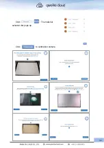
Page 39: ...Click The material selection list pops up Click to calibration camera 35...

Page 40: ...Click the camera button to refresh the processing page image is TRACE is mouse selection tool is revocation tool is edo tools 36...

Page 41: ...more graphics Click Move the graphics what you like to Favorites Click it to add a text box then right of page will pop up something like this you can select Font Size Weight This is the MEMBER RIGHTS...

Page 42: ...e has six states Open means the mechine lid is open Photographing means mechine taking a picture Ready means mechine ready to process Downloading means graphics process file is downloading to your mec...

Page 43: ...you select the graphics the right of webpage will pop up the window like this There will display the height and weight of graphics W means weight H means height Language selection tool you can choose...

Page 44: ...t mm 14 14 14 15 Engraving density DPI 400 300 400 400 Cutting power 90 90 90 90 8 Processing Parameters Name Basswood MDF Acrylic Cardboard Material thickness mm 3 3 3 2 Minimum engraving power 50 40...

Page 45: ...f processing if the button turns blue for 5 seconds the processing will be canceled When WIFI is configured long pressing the button to change to purple and red to configure WIFI Rotary 1 Instructions...

Page 46: ...l and place it to other side 2 Take out the rotary open the lid of the machine and place the rotary in the lower left corner of the square hole at the bottom of the machine 42 Pull out the drawer Remo...

Page 47: ...row on the right side of the beam to the aligned position when using the No 2 rotation axis then Pull the No 2 identification arrow on the left side of the beam to the alignment position place the las...

Page 48: ...alculated After setting the focal length click print to start engraving Among them the focal length value focal length 86 2 the height of the material placed on the highest point of the rotation axis...

Page 49: ...he machine cover unplug the air plug put the rubber cap back to its original position turn the dip switch back to flat mode take out the rotary axis install the honeycomb board and drawer and turn on...

Page 50: ...set the printer head 1 Clean Cutting Deb 2 Clean The Third Mirror Gently wipe the lens with alcohol taking care not to leave fingerprints on the lens 3 Clean the laser window 1 Remove the debris from...

Page 51: ...ocus Height Enter the parameters and click Confirm to complete refer to Table 1 for focal length parameters For example when the material thickness is 2mm the Focus Height is set to 17mm 2mm 15mm Ente...

Page 52: ...Cutting material thickness 0mm 1mm 2mm 3mm 4mm 5mm 6mm 7mm 8mm 9mm Focus Height mm 17mm 16mm 15mm 14mm 13mm 12mm 11mm 10mm 9mm 8mm 48 Figure 1...

Page 53: ...2 please follow the steps below to troubleshoot Figure 2 1 The emergency stop switch is a type of master switch When the machine is in a dangerous state the power supply is cut off through the emerge...

Page 54: ...should be checked How to check the machine when it works abnormally If the machine is turned on and reset the LED light will dim and the web page will display OPEN as shown in Figure 6 check whether...

Page 55: ...ne cannot connect to wifi and the web page displays offline as shown in Figure 10 Figure 10 1 Confirm whether the wifi is placed within 3 meters from the machine and there is no wall or others blockin...

Page 56: ...the button light will be steady yellow After the processing file is received the button light will turn green and steady Click the button to process 5 When receiving the upgrade file the button light...

Page 57: ...the machine format how to realize the front and back feeding Front and back feeding method the maximum width of the material is 360mm the thickness is 5mm and the length is not limited 1 Machine drawe...

Page 58: ...ck feeding Figure15 Figure 16 8 Handling method when error is reported on the web page The red border is 5px for the cutting effective area away from the edge of the canvas blue is the engraving effec...

Page 59: ...ws Cut mode image cannot go beyond red border Reason The image being cut is beyond the red border Solution Place the image you want to cut inside the red border and print it 3 Page shows Engraving mod...

Page 60: ...ended to change the network environment The network fluctuates click the photo button preview on the page to get the photo again Figure 22 Figure 22 5 The webpage displays Photo failed No cameras foun...

Page 61: ...LightBurn 1 Preparation Connect the double ended USB cable that came with the machine to the USB cable interface of gweikecloud machine and computer Connect the other double ended USB cable to the cam...

Page 62: ...ere has a fisheye lens LightBurn will correct this it takes some effort to set up but it s worth it You need to download and print the following images The circular image is approximately 148mm x 105m...

Page 63: ...thing like the picture below with a lot of visible circles you may need to cover it with something The pattern finder is look ing for circles and if it finds anything that looks like thousands of circ...

Page 64: ...era s field of view with the printed side of the card pointing directly at the camera as shown in the small view at the top If you cannot easily match the cap tured image to the suggested image you ma...

Page 65: ...he resolution of the captured image is 640X480 higher is better The image will update as you continue to capture The first five images are the center of the view then the bottom left right and then th...

Page 66: ...ou are satisfied with a good calibration result and an undistorted image click Finish to save the result You can also click the Align Camera button on the last page to automatically take you to the ne...

Page 67: ...a movable part of the laser such as a cover as long as the camera is in the same position when it is in use as it was when it was calibrated The camera should be securely mounted in the center of the...

Page 68: ...ep Follow the instructions in order set the numbers correctly use the Frame button to check that the material lines up with the cutouts click Start when you re ready If the clipping is not correct too...

Page 69: ...as the LightBurn edit and preview windows When double clicking a red mark appears Place a marker in the center of the four targets in their numbered order 1 2 3 4 If it s not placed correctly you can...

Page 70: ...n order zoom out and verify that all four markers are visible and clearly centered on the target as follows Click Next to complete the marker placement screen then click Finish to complete the process...

Page 71: ...Now that everything is aligned open the Camera Control window again and simply click Update Overlay to capture and project whatever is in the camera view to your workspace as shown 67...

Page 72: ...ameter of the engraving cylinder of the No 1 rotary is 30 60mm 2 Toggle switch Toggle up to rotary mode down to flat mode and original position is flat mode 3 Aviation plug The aviation plug is the jo...

Page 73: ...in the lower left corner of the square hole at the bottom of the machine 3 Remove the rubber cap of the aviation plug on the back of the machine plug in the aviation plug and turn the left DIP switch...

Page 74: ...rotation axis then Pull the No 2 identification arrow on the left side of the beam to the alignment position place the laser head on the top of the material close the lid and turn on the machine 70 P...

Page 75: ...start engraving Among them the focal length value focal length 86 2 the height of the material placed on the highest point of the rotation axis from the desktop the tool box is equipped with a height...

Page 76: ...ck to its original position turn the dip switch back to flat mode take out the rotary axis install the honeycomb board and drawer and turn on the machine again to use the flat mode 72 Take out the rot...

Reviews: