background image

- 19 -

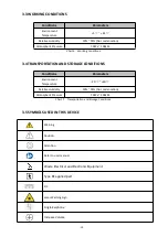
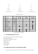
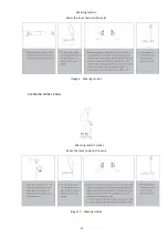
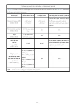
Image 8 Wearing Solutions
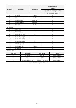
Item
No.

Part Name

Part
Model

Wearing Solution 1

Waist

Wearing Solution 2

Cane

Wearing Solution

3

Vamp

1

AI Center

PU100

1

1

1

2

Laser

L100

1

1

2

3

Collector(Left)

SM120L

1

1

4

Collector(Right)

SM120R

1

1

5

Earphone

E100

1

1

1

6

Waist Belt

-

1

7

Cane Strap

-

1

8

Ankle Strap (Left)

-

1

1

9

Ankle Strap (Right)

-

1

1

11

Vamp Strap (Left)

-

1

12

Vamp Strap

-

1

Chart 11 Wearable Parts Configuration

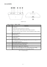
5.2 PREPARATION BEFORE INITIAL USE

Before using for the first time, please follow the steps below to prepare:
1. Choose your wearing solution
2. Download and install the application software
3. Registration and Sign in
4. Device binding
5. Device networking
6. Mode configuration
7. Use the product

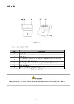
5.2.1 DOWNLOAD AND INSTALL THE APPLICATION SOFTWARE

The product must be used in conjunction with the mobile application software "SKYWALK". Please obtain

Summary of Contents for Freezing of Gait Aid System

Page 1: ...1 User Manuals Freezing of Gait Aid System GA100 IFU EN V1 1...

Page 2: ...RY Version No Contents and reasons for revision Revision date Reviser V1 0 New Fiction 2021 11 03 Qianyu Liu V1 1 Update the content according to the requirements of external inspection agencies 2022...

Page 3: ...s CO LTD Address A805 A806 Shenzhen Institute of Industry University Research of HUST No 9 Yuexing 3rd Road Science Park Nanshan District Shenzhen 518000 P R China Tel 0086 755 86724035 Email service...

Page 4: ...4 2 INDICATING LIGHT DESCRIPTION 18 5 OPERATION DESCRIPTIONS 18 5 1 WEARING SOLUTIONS 18 5 2 PREPARATION BEFORE INITIAL USE 19 5 2 1 DOWNLOAD AND INSTALL THE APPLICATION SOFTWARE 19 5 2 2 USER REGISTR...

Page 5: ...CLEANING AND DISINFECTION 30 7 MAINTENANCE 30 8 TROUBLESHOOTING 30 9 PRECAUTIONS 31 10 CONTRAINDICATIONS 32 11 EMC INFORMATION 33 13 LIMITED WARRANTY 38 14 DISPOSAL 39 15 COPYRIGHT AND RESPONSIBILITY...

Page 6: ...n which if not avoided could result in death or serious injury Caution Indicates a potentially hazardous situation which if not avoided may result in invalid data collecting damage to the equipment or...

Page 7: ...nnected to other devices at the same time the total amount of leakage current may exceed the allowable limit and pose a potential hazard to the patient 11 Equipment or devices interconnected with this...

Page 8: ...ill necessary to take protective measures for falls while using this product CAUTION 1 Please do not use this product while charging 2 If the product accidentally falls into water or other liquid duri...

Page 9: ...e same time the product records the information of the user s frozen gait which can assist the doctor to quantitatively evaluate the patient s symptoms Image 1 Freezing of Gait Aid System 3 2 COMPOSIT...

Page 10: ...phone E100 1 Accessories 6 Waist belt 1 7 Cane strap 1 8 Ankle strap Left 1 9 Ankle strap Right 1 10 Vamp strap Left 1 11 Vamp strap Right 1 12 USB charging cable 1 13 Charging base CB100 1 14 Hand St...

Page 11: ...o turn it off 2 Volume button Increase the volume 3 Volume button Decrease the volume 4 The indicating light shows the working status of the AI center For details see 4 3 Indicating Light Description...

Page 12: ...laser node For details see 4 3 Indicating Light Description 4 The rotating shaft can be rotated to adjust the direction of the laser line 5 Laser warning label 6 Charging hole for plugging in the cha...

Page 13: ...Part Description 1 Indicator arrow for wearing direction 2 The indicating light shows the working status of the collector for details see 4 3 Indicating Light Description 3 Wearing location identifier...

Page 14: ...14 3 2 4 EARPHONE Image 6 Single hole earphone Part Description 1 Earplug 2 Earphone cable 3 Audio plug Chart 5 Earphone 3 2 5 ACCESSORIES Image 7 Accessories...

Page 15: ...ION AND STORAGE CONDITIONS Conditions Parameters Environment Temperature 20 60 Relative Humidity 10 95 No condensation Atmospheric Pressure 70kPa 106kPa Chart 7 Transportation and Storage Conditions 3...

Page 16: ...rt two kinds of node configuration A B three wearing solutions 1 2 3 Identification frequency Range 4 7Hz Precision 1Hz Response time 3s Audio hint Support Audio rhythm Fast Middle Slow Users can use...

Page 17: ...80MHz Battery Capacity DC 3 7V 210mAh lithium battery Laser Wavelength 514nm Power 0 316mW Size Approximately 56 L 50 9 W 17 H mm Weight Approximately 38g Charging Voltage DC 5V Charging Time 4 h Coll...

Page 18: ...een breathing Standby mode Green Charging completed Normal Operation Yellow flashing Node not connected sensor is invalid Yellow Low battery status Charging not fully charged Blue flashing Upgrading R...

Page 19: ...ght 1 1 11 Vamp Strap Left 1 12 Vamp Strap 1 Chart 11 Wearable Parts Configuration 5 2 PREPARATION BEFORE INITIAL USE Before using for the first time please follow the steps below to prepare 1 Choose...

Page 20: ...markets download and install it You can also go to http www gyenno com to download the application Operating Environment Hardware Configuration RAM 1 GB ROM 8 GB Screen 4 7 inches Software Environmen...

Page 21: ...sure that the AI center is in a WiFi environment open SKYWALK APP and follow the instruction of Network connection to complete the connection 4 If the connection is successful Connection successful wi...

Page 22: ...ne and follow the Mode Configuration guide to complete the node configuration 5 If the mode configuration is successful Configuration Successful will pop up on SKYWALK APP 6 If the mode configuration...

Page 23: ...nly audio hint is turned on 3 Laser hint and audio hint are simultaneously turned on User can set the parameters in the APP 1 The duration of laser and audio hint after each trigger 2 Beat rhythm of t...

Page 24: ...24 Wearing mode 1 Wear the laser node on the waist Image 9 Wearing mode 1 2 WEARING MODE 2 CANE Wearing mode 2 cane Wear the laser node on the cane Image 10 Wearing mode 2...

Page 25: ...left and right ankle straps is different from each other please distinguish them before use 2 The laser head of laser node must face down 3 Ensure that the AI center is within 3 meters from the collec...

Page 26: ...on normally it can be used while walking 1 Real time detection and automatic analysis to recognize user s walking gait 2 When the frozen gait occurs laser hint audio hint or both hints will be trigge...

Page 27: ...projection position of the laser line the distance between the laser line and the user should be controlled at 20 50cm as shown in Image 25 Image 25 Laser node 2 Direction adjustment Rotate the lens...

Page 28: ...e cloud while charging 3 Data transfer will start once a wireless connection is successfully set up When transferring data the indicating light of AI center indicator will flash in blue and when the p...

Page 29: ...de from the straps It is suggested that the device should be cleaned each time after using 5 4 2 CHARGING Image 27 Charging base Name Charging base Model CB100 Serial Description 1 AI center charging...

Page 30: ...d detergent then rinse it off 7 MAINTENANCE The device consists of sophisticated mechanical parts Performance and service life of this device may be significantly reduced if under long term magnetic i...

Page 31: ...ot please re network according to the Mode Configuration section Unable to transmiss data 1 The device is not bound to the APP Please try again according to the Device Binding section 2 The wireless n...

Page 32: ...NTRAINDICATIONS Do not use the device for patients with implanted metal such as pacemakers nerve stimulators and artificial metal heart valves Users who have other metal implants should follow doctor...

Page 33: ...ssion CISPR 11 Class B The device is suitable for use in all establishments other than domestic establishments and those directly connected to the public low voltage power supply network that supplies...

Page 34: ...the relative humidity should be at least 30 Electrical fast transient burst IEC EN 61000 4 4 2 kV for power supply lines N A N A Surge IEC EN 61000 4 5 1 kV for line to line 2 kV for line to ground N...

Page 35: ...V m 80 MHz to 2 7 GHz Comply with table 1 1 2 80 MHz to 800 MHz 2 3 800 MHz to 2 7 GHz d 6 E at RF wireless communications device bands Portable RF communications device including peripherals such as...

Page 36: ...553 MHz to 13 567 MHz 26 957 MHz to 27 283 MHz and 40 66 MHz to 40 70 MHz The amateur radio bands between 0 15 MHz and 80 MHz are 1 8 MHz to 2 0 MHz 3 5 MHz to 4 0 MHz 5 3 MHz to 5 4 MHz 7 MHz to 7 3...

Page 37: ...ce can help prevent electromagnetic interference by maintaining a minimum distance between portable and mobile RF communications device transmitters and the device as recommended below according to th...

Page 38: ...ards that were developed by independent scientific organizations through periodic and thorough evaluation of scientific studies The standards include a substantial safety margin designed to assure the...

Page 39: ...local recycling companies for the possibility of re use Comply with relevant laws and regulations when disposing wasted parts and components This device should be disposed as electronic waste 15 COPYR...

Reviews: