background image

9

FTR7 INDOOR RACER

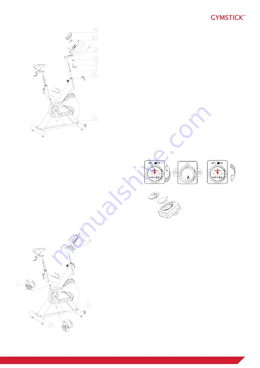
STEP 3

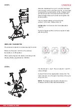
Slide the Handlebar Post (pt.17) into the handlebar 

post housing on the main frame (pt.16). You will have 

to slacken the knurled section of the L Shape Knob

(pt.26) and pull the knob back and then select the 

desired height. Release the knob and retighten the 

knurled portion.

Then fix the Handlebar (pt.18) with a flat

washer 1 (20) and L Shape knob (19)

ATTENTION: 

YOU SHOULD FIX THE HANDLEBAR 

TIGHTLY.

Fix the Computer (pt79) onto the Computer Holder 

with bolt (pt.83).

STEP 4

The Pedals (pt.1 L & pt.1 R) are marked ”L” and ”R” - 

Left and Right. 

Connect them to their appropriate crank arms. The 

right crank arm is on the right- hand side of the cycle 

as you sit on it. 

NOTE: 

The Right pedal should be threaded on 

clockwise and the Left pedal anticlockwise.


WIRELESS TRANSMITTER

The wireless transmitter is located nearby the crank.   

Make sure the power switch on the wireless  

transmitter is in ON position.

When needed replace the battery according to the 

drawing. Battery specifications: CR2032

Summary of Contents for FTR7 INDOOR RACER

Page 1: ...SER MANUAL IMPORTANT Read all instructions carefully before using this product Retain this owner s manual for future reference The specifications of this product may vary from this photo subject to ch...

Page 2: ...e exercise to make you feel better look better and enjoy life to its fullest TABLE OF CONTENT 1 SAFETY INSTRUCTIONS 3 2 EXPLODED DRAWING 4 3 PARTS LIST 6 4 ASSEMBLY INSTRUCTION 8 6 COMPUTER OPERATION...

Page 3: ...uction manual 8 Check all bolts and other connections before using the machine for the first time and ensure that the trainer is in the safe condition 9 Hold a routine inspection of the equipment Pay...

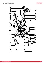
Page 4: ...4 FTR7 INDOOR RACER EXPLODED DRAWING...

Page 5: ...5 FTR7 INDOOR RACER EXPLODED DRAWING...

Page 6: ...6 FTR7 INDOOR RACER PARTS LIST...

Page 7: ...7 FTR7 INDOOR RACER PARTS LIST...

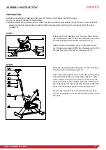
Page 8: ...M10 Domed Nut pt 6 and M8 90 Carriage bolt 3 Attach the Rear Stabilizer pt 4 to the Main Frame pt 16 using two sets of 10 Arc Washers pt 5 M10 Domed Nut pt 6 and M8 90 Carriage bolt 3 STEP 2 Slide th...

Page 9: ...THE HANDLEBAR TIGHTLY Fix the Computer pt79 onto the Computer Holder with bolt pt 83 STEP 4 The Pedals pt 1 L pt 1 R are marked L and R Left and Right Connect them to their appropriate crank arms The...

Page 10: ...he Emergency Brake function in any situation you would need it in firmly press down on the Emergency Brake Tension Control Knob 30 SEAT AND HANDLEBAR ADJUSTMENT SEAT To adjust the seat height slacken...

Page 11: ...switch to another display in every 6 seconds after exercise starts SPEED Displays the user s exercise speed TIME 1 You can press SET button to set target time between 0 00 to 99 00 for count down fun...

Page 12: ...onds and the function will be counting up from zero directly if the training is going on Press MODE button for confirmation and skip to next set up You can also press MODE button to select single func...

Page 13: ...d be part of your entire exercise routine The WARM UP is an important part of any workout It should begin every session to prepare your body for more strenuous exercise by heating up and stretching yo...

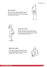
Page 14: ...t arm QUADRICEPS STRETCH With one hand against a wall for balance reach behind you and pull your right foot up Bring your heel as close to your buttocks as possible Hold for 15 counts and repeat with...

Page 15: ...TRETCH Lean against a wall with your left leg in front of the right and your arms forward Keep your right leg straight and the left foot on the floor then bend the left leg and lean forward by moving...

Page 16: ...following parts as far as included in the scope of delivery frame electronic devices wheels foot straps and pedals The guarantee does not cover Damage effected by outer force Intervention by unauthori...

Reviews: