


11
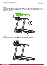
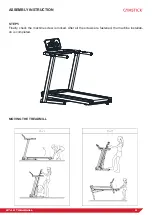
GT4.0 TREADMILL
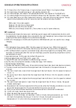
CONSOLE OPERATION INSTRUCTIONS
6. The gradient incline key, the gradient addition in a running state.
7. The gradient decline key, in the running state, is the gradient decline key.
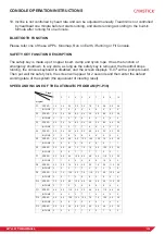
INTRODUCTION TO THE CONVERSION OF KM TO MILE
1. Unlocking the safety key and pressing the ”program” and ”mode” keys at the same time, the
display screen shows a 0.6 means conversion from km to mile;
2. Unlocking the safety key and pressing the ”program” and ”mode” keys at the same time, the
display screen shows a 1. 0 means conversion from mile to kilometer;
CONSOLE OPERATION INSTRUCTION
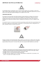
1. Put the power cord into the electrical outlet with 10A. Flip this switch to the “ON” position. The
screen shines with prompt sound and then the safety key is recognized.
2. Put the safety key in the position on the console, clip the safety key to the clothes in front of
the chest, and the screen will appear for 2 seconds and then enter default working mode. All
the counters are zero, the set value is reset, The treadmill is in the positive timing mode of the
P0 Normal Mode.
3. Press PROG key to cycle select the program P1~P36, U1,U2,U3 and FAT.
4. P1 is user program. Press MODE cycle select four training mode. User can select the speed
and inclination. Speed default is 1.0km/h, inclination default is 0%.
5. Training model 1: Positive counting of time, time, distance and calories. The select function is
closed.
6. Training model 2: Time Countdown, under selecting, time window flicker, press “+” or ”-“ to
modify the value. The range is 5-99 minute. Default is 30:00.
7. Training model 3: Calories Countdown. Under selecting, calories window flicker, press “+” or ”-“
to modify the value. The range is 20-9990CAL. Default is 50CAL.
8. Training mode 4: Distance Countdown. Under selecting, Distance window flicker, press “+” or
”-“ to modify the value. The range is1.0-99.0km. Default is1.0KM.
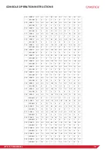
9. P1-P36 (preset programs). Only for Time Countdown mode. Under selecting, time window
flicker, press “+” or ”-“ to select. The range is 5-99 minute. Default is 30:00. Press “MODE” key to
return to Defaults.
10. Press START after setting up training mode, screen display 5 seconds into the countdown,
accompanied by five hint sound, after the countdown to 1, treadmill start gently; speed up
slowly to the display, then the constant speed operation smoothly.
11. During running, press the “+ “ or “–” or quick speed key to adjust the speed you want.
12. For P1 - P36, Speed is divided into 10 segments. Each segment has same time. The speed
after selecting will be avail in current segment. When run to next segment. It will sound 3 times
in advance. When finish 10 segments, the motor will stop with a long prompt sound.
13. Press START key when on standby mode, the motor will start working.
14. Press “STOP” key when running, the treadmill will slowly till stop. All will return to the default
state.
15. In any state, pull-out safety locks, window displays: E-07and sound buzzer. The treadmill stop.
16. The electric control system is always under inspection. Treadmill will stop once the abnormal
case happen. Window will show the ERR message and sound.
17. BODY FAT FUNCTION. When the treadmill is stopped, press the PROG key until select FAT
and enter into body fat function, on the left side DISTANCE window display program number,
press MODE key to select, on the right side, SPEED window display parameters, press or
to set up parameters.


