10
GX8.0 CROSSTRAINER
ASSEMBLY INSTRUCTION
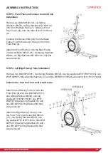
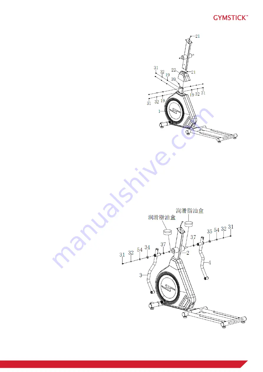
STEP 3. Front Post and Tension Control Knob
Installation
Remove six Bolts M8*20 (31), six Spring
Washers Ø8(32), six Big Washers Ø8* Ø20*2.0
(19) from the Main Frame (1). Slide the Front
Post Cover (22) onto the tube of the Front Post
(2).
Connect the Sensor Wire (39) from the Main
Frame (1) with the Sensor Wire (21) from the
Front Post (2).
Attach the Front Post (2) onto the Main Frame
(1) with six Bolts M8*20 (31) ,six Spring Washers
Ø8(32), six Big Washers Ø8* Ø20*2.0 (19) that
were removed .
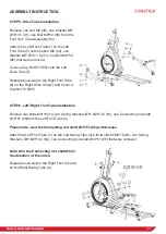
STEP 4. Left/Right Swing Tube Installation
Remove two Bolt M8*20(31), two Spring Washers Ø8(32), two big washers Ø19* Ø38*3.0(34), two
Ø19* Ø29*0.5 Wave Spring Washers(37) and two Ø8*Ø25*2.0 Big Washers(54) from Front Post(2).
Please note: coat the Front Post with Grease.
Attach the Left Swing Tube (3) onto the
Front Post (2) with one Bolt M8*20 (31),
one Spring Washer Ø8(32), one big
washer Ø19* Ø38*3.0(34), one Ø19*
Ø29*0.5 Wave Spring Washer(37) and
one Ø8* Ø25*2.0 Big Washer(54) that
were removed.
Attach the Right Swing Tube (4) onto
the Front Post (2) with one Bolt M8*20
(31), one Spring Washer Ø8(32), one
big washer Ø19* Ø38*3.0(34), one Ø19*
Ø29*0.5 Wave Spring Washer(37) and
one Ø8* Ø25*2.0 Big Washer(54) that
were removed.


