background image

12

GX8.0 CROSSTRAINER

ASSEMBLY INSTRUCTION

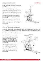
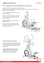
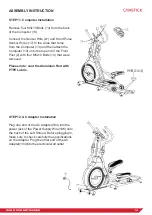
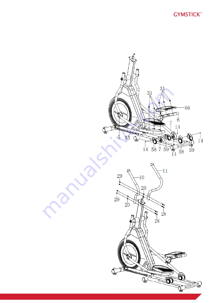
STEP 7. Left/Right Foot Pedal and Left/Right Roller cover Installation

Remove four Screw M5*10 (14) from the Drive Tube (7).

Attach two sets of Left/Right Roller covers (58/59) onto two Drive Tube(7) with four Screw 

M5*10(14) that were removed.

Remove three Screws M8*20 (31) from the 

Left Foot Tube (5).

Attach the Left Foot Pedal (55) onto the Left 

Foot Tube (5) with three M8*20 Bolts (31) 

that were removed.

Remove three M8*20 Bolts (31) from the 

Right Foot Tube (6). 

Attach the Right Foot Pedal (56) onto the 

Right Foot Tube (6) with three M8*20 Bolts 

(31) that were removed.

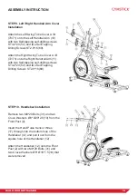
STEP 8. Handrail Arm Installation

Attach the Left Handrail Arm (10)onto the Left 

Swing Tube(3) with two Bolts M8*49(28), two 

Cruve Washers Ø8* Ø16*1.5(20), and Cap 

Nut M8(29).

Attach the Right Handrail Arm (11) onto 

the Right Swing Tube(4) with two Bolts 

M8*49(28), two Cruve Washers Ø8* 

Ø16*1.5(20), and Cap Nut M8(29).

Summary of Contents for GX8.0

Page 1: ...USER MANUAL IMPORTANT Read all instructions carefully before using this product Retain this owner s manual for future reference The specifications of this product may vary from this photo subject to change without notice ...

Page 2: ...etter look better and enjoy life to its fullest TABLE OF CONTENT 1 SAFETY INSTRUCTIONS 3 2 EXPLODED DRAWING 4 3 PARTS LIST 6 4 HARDWARE PACKING LIST 8 5 ASSEMBLY INSTRUCTION 9 6 COMPUTER OPERATION INSTRUCTIONS 15 7 MAINTENANCE 19 8 TROUBLESHOOT 19 9 WARM UP AND COOL DOWN ROUTINE 20 10 IMPLIED WARRANTY 23 READ AND FOLLOW THE SAFETY INSTRUCTIONS FAILURE TO FOLLOW THESE INSTRUCTIONS CAN RESULT IN SER...

Page 3: ...s not recommended by the manufacturer 7 Assemble the machine exactly as the descriptions in the instruction manual 8 Check all bolts and other connections before using the machine for the first time and ensure that the trainer is in the safe condition 9 Hold a routine inspection of the equipment Pay special attention to components which are the most susceptible to wear off i e connecting points an...

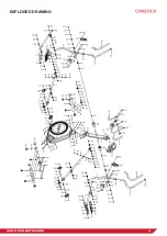
Page 4: ...4 GX8 0 CROSSTRAINER EXPLODED DRAWING ...

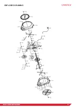
Page 5: ...5 GX8 0 CROSSTRAINER EXPLODED DRAWING ...

Page 6: ...ting rod small bushing Ø18 Ø8 10 4 025 End Cap for Handlebar Ø50 2 026 Handlebar Foam Grip Ø31 Ø37 700 2 027 Bushing 2 028 Bolt M8 49 4 No Description Qty 029 Cap Nut M8 8 030 Cap Nut Ø38 2 031 Bolt M8 20 19 032 Spring Washer Ø8 14 033 Washer Ø8 Ø33 2 0 2 034 Big Washer Ø19 Ø38 3 0 4 035 POM Bushing Ф27 11 16 036 Plastic Bushing Ø38x24 16 037 Wave Spring Washer Ø19 Ø29 0 5 2 038 Shaft Sleeve 2 039...

Page 7: ...Wheel 1 077 Washer Ø12 Ø6 1 0 1 078 Bolt M6 12 1 079 Spring Washer Ø6 6 080 Circlip Ø20 1 0 2 081 Wave Washer Ø20 Ø24 0 3 1 082 Bearing 6004 2Z 2 083 Bolt M6 15 4 No Description Qty 084 Nut M6 4 085 Belt Pulley 1 086 Straight Spindle Assembly 1 087 Belt 1 088 Plastic BoltΦ8x32 2 089 Left Cain Cover 1 090 Right Cain Cover 1 091 Nut M10x1 25 2 092 Turntable Assembly 2 093 Screw ST4 2 25 6 094 Turnta...

Page 8: ...8 GX8 0 CROSSTRAINER HARDWARE PACKING LIST ...

Page 9: ...ront Stabilized 9 STEP 2 Front Stabilized and Rear Main Frame Installation Attach the Rear Main Frame 8 onto the Main Frame 1 with two M8 80 Bolts 51 two Ø8 Ø20 2 0 Big Wave Washers 43 two Ø8 Spring Washers 32 two M8 Cap Nuts 29 Attach the Front Stabilized 9 onto the Main Frame 1 with two M8 75 Bolts 42 two Ø8 Ø20 2 0 Big Wave Washers 43 two Ø8 Spring Washers 32 two M8 Cap Nuts 29 ...

Page 10: ...emoved STEP 4 Left Right Swing Tube Installation Remove two Bolt M8 20 31 two Spring Washers Ø8 32 two big washers Ø19 Ø38 3 0 34 two Ø19 Ø29 0 5 Wave Spring Washers 37 and two Ø8 Ø25 2 0 Big Washers 54 from Front Post 2 Please note coat the Front Post with Grease Attach the Left Swing Tube 3 onto the Front Post 2 with one Bolt M8 20 31 one Spring Washer Ø8 32 one big washer Ø19 Ø38 3 0 34 one Ø19...

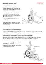
Page 11: ... Foot Tube 6 on the Right Drive Tube 7 and Cover a Cap Nut S13 65 STEP 6 Left Right Foot Tube Installation Remove two Bolts M8 16 23 two Spring Washers Ø8 Ø25 2 0 54 one Connecting rod shaft Ø19 61 68 from the Left Foot Tube 5 Please note coat the Connecting rod shaft Ø19 61 68 with Grease Attach the Left Foot Tube 5 on the Left Swing Tube 3 with two Bolts M8 16 23 two Spring Washers Ø8 Ø25 2 0 54...

Page 12: ...eft Foot Pedal 55 onto the Left Foot Tube 5 with three M8 20 Bolts 31 that were removed Remove three M8 20 Bolts 31 from the Right Foot Tube 6 Attach the Right Foot Pedal 56 onto the Right Foot Tube 6 with three M8 20 Bolts 31 that were removed STEP 8 Handrail Arm Installation Attach the Left Handrail Arm 10 onto the Left Swing Tube 3 with two Bolts M8 49 28 two Cruve Washers Ø8 Ø16 1 5 20 and Cap...

Page 13: ...nto the Right Handrail Arm 11 with two Self tapping self drilling screws ST4 2 20 52 and two Self Tapping Drilling Screws ST2 9 16 69 STEP 10 Handlebar Installation Remove two M8 20 Bolts 31 and two Cruve Washers Ø8 Ø20 2 0 19 from the Front Post 2 Insert the Hand Pulse Sensor Wires 17 through into the bottom hole of the Handlebar 12 and pull it out from the square hole of the Handlebar 12 Attach ...

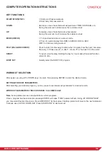
Page 14: ... the top end of the Front Post 2 with four M5x10 Bolts 14 that were removed Please note coat the Aluminum Rod with PTFE Lubric STEP 12 AC Adapter Installation Plug one end of the AC Adapter 104 into the power jack of the Power Supply Wire 106 onto the back of the Left Shroud Before plugging in make sure to check carefully the specifications on the Adapter Plug the other end of the AC Adapter 104 i...

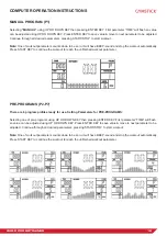
Page 15: ...ess Level 1 6 after 1 minute F1 is the best F6 is the worst RESET To reset current setting Holding the key for 3 seconds will reset all function values to zero BODY FAT Quickly select the BODY FAT program WORKOUT SELECTION After power up using UP or DOWN keys to select then pressing ENTER to enter the desired mode SETTING WORKOUT PARAMETERS After selecting your desired program you may pre set seve...

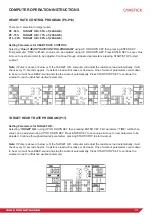
Page 16: ...Press START KEY to continue the workout to reach the unfinished workout parameter PRE PROGRAMS P2 P7 There are 6 program profiles ready for use Setting Parameters for PRE PROGRAMS Selecting one of pre programs using UP OR DOWN KEY then pressing ENTER KEY First parameter TIME will flash so value can be adjusted using UP OR DOWN KEY Press ENTER KEY to save value move to next parameter to be adjusted...

Page 17: ...increase or decrease One of workout parameters counts down to be zero it will have BEEP sound and stop the workout automatically Press START STOP KEY to continue the workout to reach unfinished workout parameter TARGET HEART RATE PROGRAM P11 Setting Parameters for TARGET H R Selecting TARGET H R using UP OR DOWN KEY then pressing ENTER KEY First parameter TIME will flash so value can be adjusted u...

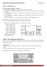
Page 18: ... BMR BMI and BODY TYPE Note There are 9 body types divided according to BODY FAT calculated Type 1 is from 5 to 9 Type 2 is from 10 to 14 Type 3 is from 15 to 19 Type 4 is from 20 to 24 Type 5 is from 25 to 29 Type 6 is from 30 to 34 Type 7 is from 35 to 39 Type 8 is from 40 to 44 Type 9 is from 45 to 50 BMR Basal Metabolism Ratio BMI Body Mass Index CONNECT THE INSTRUMENT POWER SUPPLY Plug one en...

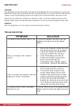
Page 19: ...ner There is no display on the computer console 1 Remove the computer console and verify the wires that come from the computer console are properly connected to the wires that come from the front post 2 Check if the batteries are correctly positioned and battery springs are in proper contact with batteries 3 The batteries in the computer console may be dead Change to new batteries There is no hear...

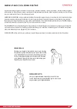
Page 20: ...ld be part of your entire exercise routine The WARM UP is an important part of any workout It should begin every session to prepare your body for more strenuous exercise by heating up and stretching your muscles increasing your circulation and pulse rate and delivering more oxygen to your muscles COOL DOWN at the end of your workout repeat these exercises to reduce soreness in tired muscles HEAD R...

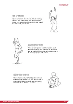
Page 21: ...ft arm QUADRICEPS STRETCH With one hand against a wall for balance reach behind you and pull your right foot up Bring your heel as close to your buttocks as possible Hold for 15 counts and repeat with left foot INNER THIGH STRETCH Sit with the soles of your feet together and your knees pointing outward Pull your feet as close to your groin as possible Gently push your knees toward the floor Hold f...

Page 22: ...STRETCH Lean against a wall with your left leg in front of the right and your arms forward Keep your right leg straight and the left foot on the floor then bend the left leg and lean forward by moving your hips toward the wall Hold then repeat on the other side for 15 counts TOE TOUCHES Slowly bend forward from your waist letting your back and shoulders relax as you stretch toward your toes Reach ...

Page 23: ...e following parts as far as included in the scope of delivery frame electronic devices wheels foot straps and pedals The guarantee does not cover Damage effected by outer force Intervention by unauthorized parties Incorrect handling of the product Non compliance of the operating instructions Note Wear parts and expendable parts are also not covered The device is intended for home use Manufactured ...

Reviews: