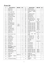
background image


19 

Parts list 

#.   

DESCRIPTION


REMARK


QTY


#.   

DESCRIPTION


REMARK


QTY


Main frame 


39 

Start/stop Pulse 


Base frame 


40 

Control circuit board 


Left upright tube 


41 

Computer 

bottom 

wire 


Right upright tube 


42 

Computer up wire 


Motor bracket 


43 

Rubber pad 2 


Computer bracket 


44 

Magnetic Ring 


Rubber pad 


45 

Blue Single-Line 


Rotating tube 


46 

Hexagon cap screw 

M8*25 

Front roller 


47 

I - Hexagon nuts 

M6 

10 

Back roller 


48 

Screw   

ST4.2*19 

11 

Air Pressure Bar 


49 

Hexagon cap screw 

M6*55 

12 

5# Allen Wrench 

5mm 

50 

Hexagon cap screw 

M6*65 

13 

Cross Bolt 

M5*15 

51 

Hexagon cap screw 

M8*16 

10 

14 

DC Motor 


52 

Hexagon cap screw 

M8*12 

15 

Running Board 


53 

Hexagon cap screw 

M8*40 

16 

Adjust food pad 


54 

Hexagon cap screw 

M10*70 

17 

Circle plug                                                                                                                                                                                           


55 

Flat Washer C Class 

18 

Motor cover 


56 

Screw 

ST4.2*12 

10 

19 

Motor bottom cover 


57 

Cross 

pan 

had 

screw 

M5*8 

20 

Side staps 


58 

I - Hexagon nuts 

M8 

21 

Right end cap 


59 

I - Hexagon nuts 

M10 

22 

Left end cap 


60 

I-Hexagon nuts 

M8 

23 

Fixing Plug 


61 

Oil bottle 


24 

Drive belt 


62 

screw 

ST4.8*19 

25 

Power cord 


63 

Lock Washer 

26 

Running belt 


64 

Lock Washer 

16 

27 

Foot pad 


65 

Lock Washer 

28 

Ring  shaped  power 
line plug A 


66 

Lock Washer 

10 

29 

Transport wheel 


67 

Spring washer 

30 

Wheel cover 


68 

Hexagon cap screw 

M6*27 

31 

Standard power cord 


69 

Hexagon cap screw 

M6*30 

32 

Power Switch 


70 

Hexagon cap screw 

M8*45 

33 

Foam grip 


71 

Safety Key 


34 

Screw 

ST4.2*13 

72 

Safety Key inductor 


35 

Computer 

bottom 

cover 


73 

Safety  Key  metal 
plate 


36 

Computer shrouding 


74 

Computer 

face 

sticker 


Summary of Contents for RUN 3.0

Page 1: ...1 RUN 3 0 TREADMILL USER MANUAL...

Page 2: ...ty precautions 3 Assembly instructions 4 Folding instructions 5 6 Technical parameters 8 Grounding method 8 Operation guide 9 12 Learning Guide 13 14 Warm up instructions 15 Maintenance guide 16 Runni...

Page 3: ...y from the treadmill while starting workout 7 Don t exercise in 40 Mints after dinner 8 The equipment is suitable for adults Juveniles need be accompanied with adults while workout 9 You must hold on...

Page 4: ...n PART LIST NO DES Specification N os NO DES Specification Nos 1 Main Frame 1 64 Lock washer 8 8 12 5 Allen Wrench 5mm 1 70 Bolt M8 45 2 51 Bolt M8 16 1pc preassemble 6 71 Safety lock 1 61 Oil bottle...

Page 5: ...d lock washer 64 to the base frame through base and right upright tube Notice Support the upright with hand avoid falling down to have any hurt 1 Remove 1pc bolt M8 16 51 from the computer frame Holdi...

Page 6: ...up the main frame until hearing the sound that th ATTENTION Please make sure all parts have been fixed properly Before you use the treadmill please read the instruction carefully Attach the safety ke...

Page 7: ...t position A till hearing the sound that the air pressure bar B is locked into the round tube Support place A with hand kick the place of air pressure bar then the base frame will fall down automatica...

Page 8: ...e plug must be plugged into an appropriate outlet that is properly installed and grounded in accordance with all local codes and ordinances DANGER Improper connection of the equipment grounding conduc...

Page 9: ...e 3 BUTTON FUNCTION PROG Program select key In order Manual Mode P1 P2 P12 FAT MODE Count Down Mode Select key In order Manual Mode Time counts down Distance count down Calorie count down START Press...

Page 10: ...o 20 segments each time the running time for the set 20 Press the START button treadmill running according to the first paragraph in 3 seconds countdown speed when ended automatically enter the next p...

Page 11: ...parison Body fat index BMI Obesity level 19 Too thin 19 26 normal 26 30 overweight 30 Too fat 7 Audio features OPTION IF HAVE Put external audio equipment such as MP3 audio through random add audio li...

Page 12: ...2 3 3 4 5 3 4 5 5 3 4 5 4 4 4 2 3 3 5 3 P2 SPEED 2 4 4 5 6 4 6 6 6 4 5 6 4 4 4 2 2 5 4 2 P3 SPEED 2 4 4 6 6 4 7 7 7 4 7 7 4 4 4 2 4 5 3 2 P4 SPEED 3 5 5 6 7 7 5 7 7 8 8 5 9 5 5 6 6 4 4 3 P5 SPEED 2 4...

Page 13: ...ts by the velocity 4 4 8KM H then slowly increase the speed by 0 3KM H 2Mints until up to the stable speed which you feel is comfortable for 45Mints For improving the intensity of movement you can mai...

Page 14: ...Speed 6 0 7 5KM H Fast walking Speed 7 5 9 0KM H Jogging Speed 9 0 12 0KM H intermediate speed walking Speed 12 0 14 5M H well experiences of running Speed 14 5 16 0KM H excellent runner SAFETY TRAINI...

Page 15: ...clean seat put one leg straight Inward close to the other leg to make it close to the inside leg straight Try to touch the toes with your hands Maintain 10 to 15 seconds then relax Repeat for each le...

Page 16: ...e the motor cover and vacuum under the motor cover RUNNING BELT AND DECK LUBRICATION This treadmill is equipped with a pre lubricated low maintenance deck system The belt deck friction may play a majo...

Page 17: ...om the deck about 50 75mm on both sides Center the Running Belt Place treadmill on a level surface Run Treadmill at approximately 6 8KM H checking the running condition If the belt has drifted to the...

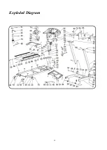
Page 18: ...18 Exploded Diagram...

Page 19: ...3 16 Adjust food pad 2 54 Hexagon cap screw M10 70 2 17 Circle plug 2 55 Flat Washer C Class 8 7 18 Motor cover 1 56 Screw ST4 2 12 10 19 Motor bottom cover 1 57 Cross pan had screw M5 8 4 20 Side st...

Page 20: ...the connection wire between computer and control board was well connected 2 Make sure the IC on the control board was well inserted If not re insert 3 Abnormal power supply in control board Please ch...

Page 21: ...ght tool Prepare an area to assemble Follow the instruction accordingly Never force the joints Periodically tighten the joints Keep this manual with you Insert each fixing pin 23 into the holes of the...

Page 22: ...act the dealer of this product within the guarantee period The warranty applies to the following parts as far as included in the scope of delivery Frame cable electronic devices wheels pedals The guar...

Reviews: