background image

42

GYSPOT INVERTER PTI.G

EN

RECOMMENDATIONS FOR WELDING AREA ASSESSMENT AND WELDING

Miscellaneous

The user is responsible for the correct installation and usage of the welding material based on the instructions supplied by the manufacturer. If 

electromagnetic disturbances are detected, it is the user’s responsibility to resolve the situation with the manufacturer’s technical assistance. In some 

cases, this corrective action may be as simple as earthing the welding circuit. In other cases, it may be necessary to construct an electromagnetic 

shield around the welding power source and around the entire piece by fitting input filters. In all cases, electromagnetic interferences must be reduced 

until they are no longer inconvenient.

Welding area assessment

Before installing the machine, the user must evaluate the possible electromagnetic problems that may arise in the area where the installation is 

planned. The following must be taken into account:

a) the presence (above, below and next to the arc welding machine) of other power cables, remote cables and telephone cables;

b) television transmitters and receivers;

c) computers and other hardware;

d) critical safety equipment such as industrial machine protections;

e) the health and safety of  people in the area especially if they are using pacemakers or hearing aids;

f) calibration and measuring equipment;

g) the isolation of other pieces of equipment which are in the same area.

The operator has to ensure that the devices and equipment used in the same area are compatible with each other. This may require extra precautions;

h) the time of day during the welding or other activities have to be performed.

The dimension of the cutting area that has to be considered depends on the size and shape of the building and the type of work undertaken. The area 

taken into consideration might go beyond the limits of the installations.

Review of the welding installation

Reviewing the welding installations can be useful to determine and resolve any case of electrical disturbances. The assessment of emissions must 

include in situ measurements as specified in Article 10 of CISPR 11: 2009. In situ measurements can also be used to confirm the effectiveness of 

mitigation measures.

RECOMMENDAED METHODS TO REDUCE ELECTROMAGNETIC EMISSIONS

a. National power grid: 

The arc welding machine must be connected to the national power grid in accordance with the manufacturer’s 

recommendation. In case of interferences, it may be necessary to take additional precautions such as the filtering of the power supply network. 

Consideration should be given to shielding the power supply cable in a metal conduit or equivalent of permanently installed arc welding equipment. It 

is necessary to ensure the electrical continuity of the frame along its entire length. The shielding should be connected to the welding current source 

to ensure a good electrical contact between the conduit and the casing of the welding current source.

b. Maintenance of the resistance welding equipment: 

The resistance welding machine should be subject to a routine maintenance check in line 

with the recommendations of the manufacturer. All accesses, service doors and covers should be closed and properly locked when the arc welding 

equipment is on. The arc welding equipment must not be modified in any way, except for the changes and settings covered in the instructions.

c. Welding cables: 

Cables must be as short as possible, close to each other and close to the ground, if not on the ground. 

d. Equipotential bonding: 

consideration should be given to bond all metal objects in the surrounding area. However, metal objects connected to 

the workpiece increase the risk of electric shock if the operator touches both these metal elements and the electrode. It is necessary to insulate the 

operator from such metal objects. 

e. Earthing of the welded part: 

When the part is not earthed - due to electrical safety reasons or because of its size or location (which is the case 

with ship hulls or metallic building structures), the earthing of the part can, in some cases but not systematically, reduce emissions It is preferable to 

avoid the earthing of parts that could increase the risk of injury to the users or damage other electrical equipment. If necessary, it is appropriate that 

the earthing of the part is done directly, but the safety rules in some countries may not allow such a direct connection and it is appropriate that the 

connection is made using a capacitor selected according to national regulations.

f. Protection and shielding: 

The selective protection and shielding of other cables and devices in the area can reduce perturbation issues. The 

protection of the entire welding area can be considered for specific situations.

TRANSPORT AND TRANSIT OF THE WELDING MACHINE

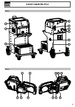
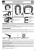
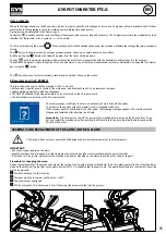
The top of the machine is equipped with handles for movement by hand. Be careful not to underestimate the weight of the 

machine. The handles cannot be used to lift the product.

Do not use the cables or torch to move the machine. Do not place/carry the unit over people or objects.

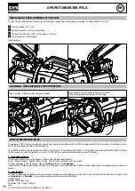
EQUIPMENT INSTALLATION


• Put the machine on the floor (maximum incline of 10°). 

• The machine must be placed in a sheltered area away from rain or direct sunlight.

• The machine protection level is IP20, which means :

- Protection against access to dangerous parts from solid bodies of a diameter ≥12.5mm and,

- Protection against water projections.

Power cables, extension leads and welding cables must be fully uncoiled to prevent overheating.

Summary of Contents for PTI.G

Page 1: ...1 73502_V2_04 03 2022 FR 2 17 17 39 105 120 GYSPOT INVERTER PTI G 400 V www gys fr EN 2 17 40 60 105 120 DE 2 17 61 82 105 120 ES 2 17 83 104 105 120...

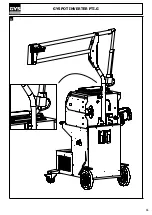
Page 2: ...2 GYSPOT INVERTER PTI G DIMENSIONS ABMESSUNGEN DIMENSIONES MONTAGE ASSEMBLY MONTAJE 3 0 1 5 1225 915 285 M5x12 x6 5 N m A A x2 x2...

Page 3: ...NGE MONTAJE DEL SOPORTE DE PINZA EN G MONTAGE SUPPORT BRAS G9 OPTION G9 ARM SUP PORT MOUNTING OPTIONAL G9 ARMST TZMON TAGE OPTIONAL G9 MONTAJE DEL SOPORTE DEL BRAZO OPCIONAL MONTAGE SUPPORT BRAS ARM S...

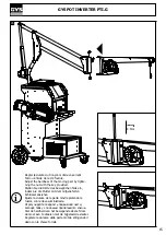
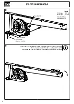
Page 4: ...The use of the bracket is strictly reserved to relieve the weight of the welding tongs It must never be used for lifting or any other application otherwise the jib crane trolley assembly may overturn...

Page 5: ...INVERTER PTI G M8 x 16 20 N m M5 x 12 4 N m 4 3 M8x16 x2 20 N m Mettre l quilibreur dans son logement Put the balancer in its housing Legen Sie den Balancer in sein Geh use i 2 M8x16 x2 M5x12 x2 20 N...

Page 6: ...5 6 M8x16 x4 M5x12 x1 20 N m 0 5 N m Rondelle M8 x2 Rondelle M5 x1 Tirer le c ble de l quilibreur pour le faire passer dans la poulie et l encoche Pull the balancer cable through the pulley and the no...

Page 7: ...7 GYSPOT INVERTER PTI G M5 x 12 4 N m 7 8 M8x16 x4 M5x12 x2 20 N m 4 N m...

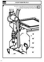
Page 8: ...INVERTER PTI G 9 Montage du palier pivot bas fourni avec la potence Mounting of the low pivot bearing supplied with the stem Montage des niedrigen Schwenklagers mit dem Vorbau mitgeliefert i M8x20 x2...

Page 9: ...OT INVERTER PTI G 10 Enclencher le frein des 2 roues avants du g n rateur Engage the brake on one of the 2 front wheels of the generator Bet tigen Sie die Bremse an einem der 2 Vorderr der des Generat...

Page 10: ...ging arm 17 4 kg Das Gewicht des Ausleger nicht untersch tzen 17 4 kg Pour faciliter le montage d montage de la potence sur le g n rateur 2 personnes sont requises In order to assemble or disassemble...

Page 11: ...11 GYSPOT INVERTER PTI G 12...

Page 12: ...INVERTER PTI G 13 Faire pivoter la potence jusqu ce que la vis se loge dans l empreinte Swivel the bracket until the screw fits into the recess Den Schaft schwenken bis die Schraube in der Aussparung...

Page 13: ...13 GYSPOT INVERTER PTI G 14 Verrouiller la potence en fixant le support Lock the gallows by fixing the bracket Verriegeln Sie den Schaft durch Sichern der Halterung i M5x12 x2 4 N m...

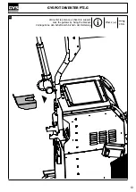
Page 14: ...uyer sur le bouton pour mettre la potence en position basse Connect the cylinder connector to the carriage Press the button to put the stem in the down position Verbinden Sie den Zylinderanschluss mit...

Page 15: ...ovided Stellen Sie die H rte des beweglichen Teils ein indem Sie die Mutter mit dem mitgelieferten Schl ssel anziehen Ajuste la dureza de la parte m vil apretando la tuerca con la llave suministrada S...

Page 16: ...erung Pour r gler la tension du c ble de l quilibreur l utilisateur doit imp rativement mettre la pince en charge sur le c ble To adjust the tension of the balancer cable the user must load the clamp...

Page 17: ...17 GYSPOT INVERTER PTI G FIG 1 FIG 2 3 4 5 1 9 10 11 7 8 6 2 6 7 1 2 3 8 9 5 4...

Page 18: ...uarantee electrical and thermal insulation Use sufficient welding protective gear for the whole body hood gloves jacket trousers varies depending on the application operation Protect the eyes during c...

Page 19: ...or as soon as possible EMC MATERIAL CLASSIFICATION This Class A machine is not intended to be used on a residential site where the electric current is supplied by the domestic low voltage power grid T...

Page 20: ...r equivalent of permanently installed arc welding equipment It is necessary to ensure the electrical continuity of the frame along its entire length The shielding should be connected to the welding cu...

Page 21: ...recommended to renew the cooling liquid every 2 years All the welding tools will wear off with use Ensure that these tools are clean to get the best results Prior to using the pneumatic clamp check t...

Page 22: ...uid gauge 5 Regulator DESCRIPTION OF THE G CLAMP FIG 2 1 Arm locking unlocking lever 7 Locking latch 2 Interchangeable arm 8 Gyro lock unlock mechanism 3 Gyroscope 9 Over opening button 4 Pneumatic bo...

Page 23: ...lug must be connected to the electrical panel and only power this equipment Check the cross section of the cable reaching the connection socket 4 x 6 mm If the power line from the switchboard is longe...

Page 24: ...AND MAINTENANCE STARTING THE MACHINE Start the machine by switching the switch on ON Fig 1 7 and stop it by switching to OFF Warning Never disconnect the power supply when the welding electrical distr...

Page 25: ...button FIG 2 12 on the clamp is used to remotely adjust the welding settings thickness type of steel Long push change of setting to go from one setting to another Short push modification of the value...

Page 26: ...pots by following the instructions of a repair book The parameters to set in this mode are Current Duration Pressure Reference of the arm used Push the button for 2 seconds to return to the AUTO mode...

Page 27: ...ay the error message maximum duration reached Push the button for 2 seconds to return to the AUTO mode SETTINGS MENU This menu is accessible by pressing and holding the button for 2 seconds The langua...

Page 28: ...wheel Select the desired tool using the and keys In Manual mode the maximum possible intensity is 8 kA for a maximum duration of 500 ms The settings showing on the screen will not exceed these values...

Page 29: ...does not happen and the fault must be skipped for the weld to happen Insufficient air pressure If the input pressure is insufficient to deliver the tightening requested the machine beeps and displays...

Page 30: ...xx V PASS or FAIL Blocking 17 IGBT test result 3 IGBT3 xxx V PASS or FAIL Blocking 18 IGBT test result 4 IGBT4 xxx V PASS or FAIL Blocking Page CHECK n 2 1 Name of the product CONNEXION TRANSFO PASS o...

Page 31: ...button starts recording the report in the selected log Pressing the record button again on off stops the current recording The log created contains an ID entered by the user as well as for each spot...

Page 32: ...tters or numbers The keys and are used to move the cursor inside the field Press the button briefly to clear the field The button allows you to scroll through the fields for editing or reading Catalog...

Page 33: ...he GYSPOT software for editing parameters on a PC is stored on the SD memory card The instructions are is stored on the SD memory card The memory space is sufficient to ensure an autonomy of more than...

Page 34: ...talled from files on the SD card In the directory GYSPOT V X XX double click on the file INSTALL EXE and follow the instructions to install the software on your PC A GYSPOT icon is automatically insta...

Page 35: ...earing an SD card Clearing the card will erase all completed spot reports recorded on the SD card To clear an SD card insert the SD card into the PC card reader and then in the menu click on Options a...

Page 36: ...figured point in the USER file Select a spot parameter from the list and click on the button to the right of the list Raison sociale Adresse Ville Code postal JBDC ZI 134 Bd des Loges 53941 Saint Bert...

Page 37: ...OFF position and disconnect the unit from the mains 2 Place a bucket min 30 l capacity under the machine drain hole 3 Unscrew the drain plug located under the machine using a 10 mm torx spanner Ref S...

Page 38: ...k the earth contact Incorrect tightening of the chuck or acces sories Check the tightness of the chuck and acces sories and the condition of the sheathing Damaged consumables Replace the consumables W...

Page 39: ...stockage liquide de refroidissement Storage temperature coolant Lagertemperatur K hlmittel Temperatura de almacenamiento del refrigerante 20 C 55 C 4 F 131 F Hygrom trie Hygrometry Max Luftfeuchtigke...

Page 40: ...106 GYSPOT INVERTER PTI G PI CES DE RECHANGE SPARE PARTS ERSATZTEILE PIEZAS DE RECAMBIO 1 2 6 7 5 4 3 16 15 14 21 9 10 18 19 20 13 12 11 8 17...

Page 41: ...ares Potentiometer 3 4Kohm Potenci metro lineal 3 4Kohm 63090 11 Gaine tiss e de Protection Diam 57mm Rlx de 50m Protective woven sheath Diam 57mm Rlx of 50m Gewebter Schutzmantel Durchm 57mm Rlx von...

Page 42: ...trodos de 4 posiciones 90148 24 Socle bras quip Equipped arm base Ausgestatteter Arm Einschubsockel Base de brazo equipad 94183 25 26 G7 25 2 lectrodes pour bras acc s difficile 2 electrodes for diffi...

Page 43: ...5138 32 Tuyau anti tincelles Anti spark hose Funkengesch tzte Leitung Conducto anti chispas 94525 33 Tuyau anti tincelles Anti spark hose Funkengesch tzte Leitung Conducto anti chispas 94512 34 2 Bras...

Page 44: ...42 44 45 43 46 47 KIT 067226 Gun 42 Cable pistolet PTI G Gun cable PTI G Pistolenkabel PTI G Cable de la pistola PTI G A0071 43 Switch pistolet 0 1A 125VAC Pistol switch 0 1A 125VAC Pistolenschalter 0...

Page 45: ...a sin escobillas 10Lit mn 24VDC 80W 71876 52 Radiateur eau 240x225x60 1 2Kw h Water radiator 240x225x60 1 2Kw h Wasserheizk rper 240x225x60 1 2Kw h Radiador de agua 240x225x60 1 2Kw h 71750 53 Bouchon...

Page 46: ...ductor PTI G E0005C Nappe 10pts 20cm Tablecloth 10pts 20cm Tischtuch 10pts 20cm Mantel 10pts 20cm 53092 62 Circuit condensateur PTI G 400 Capacitor circuit PTI G 400 Kondensatorschaltung PTI G 400 Cir...

Page 47: ...10 2 E0009 1 2 3 4 5 6 7 8 9 10 11 12 12x0 5mm 51905 97028 22 8 10 11 E0007 E0003 10 10 4 4 NC NC HT HT HT HT PM34 IGBT PM34 IGBT PM12 IGBT PM12 IGBT F4 F3 F2 F1 51131 71876 96019 KM FAN 52194 5 52344...

Page 48: ...EMBLY SCHEMATICS SCHLAUCHPAKET SCHALTPLAN ESQUEMA CABLEADO 1 2 3 4 5 6 7 8 9 10 11 12 12x0 5mm 1 2 3 4 5 6 7 8 9 10 11 63090 1 2 3 52148 52149 V V T T 92048SF RED WHITE GRAY 51381 51381 51408 71251 BL...

Page 49: ...SCHEMATICS PNEUMATISCHER SCHALTPLAN ESQUEMA NEUM TICO NETWORK PRESSURE SENSOR G PLIERS PRESSURE SENSOR 71729 EV2 EV3 EV4 71797 71741 71824 92060 SCH MA HYDRAULIQUE HYDRAULIC SCHEMATICS HYDRAULISCHER S...

Page 50: ...de refroidissement Loss of charge of the cooling liquid instructed Nominaler Druckverlust der K hlfl ssigkeit s P rdida de carga asignada del fluido de refrigeraci n Nominaal verlies koelvloeistof m M...

Page 51: ...recogida de basuras selectiva seg n la directiva europea 2012 19 UE No tirar este producto a la basura dom stica 2012 19 UE Afzonderlijke inzameling vereist volgens de Europese richtlijn 2012 19 UE G...

Page 52: ...118 SAS GYS 1 rue de la Croix des Landes CS 54159 53941 SAINT BERTHEVIN Cedex FRANCE...

Reviews: