18
1234567890123456
1234567890123456
1234567890123456
1234567890123456
1234567890123456
1234567890123456
1234567890123456
1234567890123456
1234567890123456
1234567890123456
1234567890123456
1234567890123456
1234567890123456
1234567890123456
1234567890123456
1234567890123456
1234567890123456
1234567890123456
1234567890123456
1234567890123456
1234567890123456
1234567890123456
1234567890123456
1234567890123456
1234567890123456
1234567890123456
1234567890123456
1234567890123456
1234567890123456
1234567890123456
1234567890123456
1234567890123456
1234567890123456
1234567890123456
1234567890123456
1234567890123456
1234567890123456
1234567890123456
1234567890123456
1234567890123456
1234567890123456
1234567890123456
1234567890123456
1234567890123456
1234567890123456
1234567890123456
1234567890123456
1234567890123456
1234567890123456
1234567890123456
1234567890123456
1234567890123456
1234567890123456
1234567890123456
1234567890123456
1234567890123456
1234567890123456
1234567890123456
1234567890123456
1234567890123456
1234567890123456
1234567890123456
1234567890123456
1234567890123456
1234567890123456
1234567890123456
1234567890123456
1234567890123456
1234567890123456
1234567890123456
1234567890123456
1234567890123456
1234567890123456
1234567890123456
1234567890123456
1234567890123456
1234567890123456
1234567890123456
1234567890123456
1234567890123456
1234567890123456
1234567890123456
1234567890123456
1234567890123456
1234567890123456
1234567890123456
1234567890123456
1234567890123456
1234567890123456
1234567890123456
1234567890123456
1234567890123456
1234567890123456
1234567890123456
1234567890123456
1234567890123456
1234567890123456
1234567890123456
1234567890123456
1234567890123456
1234567890123456
1234567890123456
1234567890123456
1234567890123456
1234567890123456
1234567890123456
1234567890123456
1234567890123456
1234567890123456
1234567890123456
1234567890123456
1234567890123456
1234567890123456
1234567890123456
1234567890123456
1234567890123456
1234567890123456
1234567890123456
1234567890123456
1234567890123456
1234567890123456
1234567890123456
1234567890123456
1234567890123456
1234567890123456
1234567890123456
1234567890123456
1234567890123456
1234567890123456
1234567890123456
1234567890123456
1234567890123456
1234567890123456
1234567890123456
1234567890123456
1234567890123456
1234567890123456
1234567890123456
1234567890123456
1234567890123456
1234567890123456
1234567890123456
1234567890123456
1234567890123456
1234567890123456
1234567890123456
1234567890123456
1234567890123456
1234567890123456
1234567890123456
1234567890123456
1234567890123456
1234567890123456
1234567890123456
1234567890123456
1234567890123456
1234567890123456
1234567890123456
1234567890123456
1234567890123456
1234567890123456
1234567890123456
1234567890123456
1234567890123456
1234567890123456
1234567890123456
1234567890123456
1234567890123456
1234567890123456
1234567890123456
1234567890123456
1234567890123456
1234567890123456
1234567890123456
1234567890123456
1234567890123456
1234567890123456
1234567890123456
INSTALLATION AND SERVICE MANUAL 959R
184981-02
7.3 Spigot Switch Operation
The spigot switch is designed to start the
compressor and beater motor just before
product begins to flow from the spigot. To
test and adjust the switch:
CAUTION
To avoid electrical shock or
contact with moving parts,
make sure all switches are
in the "OFF" position and
that the main power supply
is disconnected.
1. Remove the dispensing head and
view the back of the head. With the
spigot inserted in the dispense head,
turn the spigot so that the edge of the
spigot dispensing port is visible. This
is the point at which product will begin
to enter the spigot.
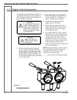
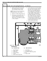
2. Mark this position on the dispensing
head and spigot with a pencil, as
shown in figure 7-1 and figure 7-2,
item C. Repeat for each spigot.
3. Install the dispensing head and
spigot rods on the freezer.
4. Slowly open the spigot. The micro
switch should click at the point the
pencil marks line up on the spigot
and head assembly.
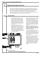
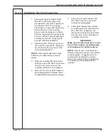
5. If the switch does not click, a switch
adjustment must be made. Remove
the cover from the electrical box and
slightly loosen the two mounting
screws (#1 Figure 7-2). Loosen the
locking nuts (2). Adjust screws (3) for
proper actuation of the switch.
6. Tighten all screws and nuts. Recheck
for proper operation.
NOTE:
Excessive force on these screws
may change the position of the switch
assembly. Once they are in place,
recheck for correct position.
7. Reconnect to main power supply.
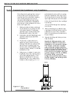
Figure 7-1
CAUTION
Make sure freezer is
depressurized before
proceeding.

