background image

ELECTRO FREEZE Shake Model CS704

185260

40

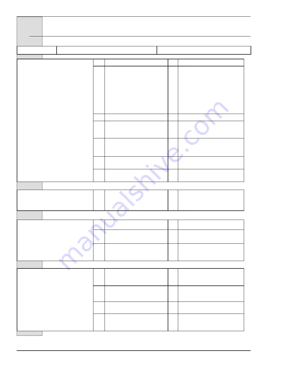
13  Troubleshooting Charts 

— continued

PROBLEM

PROBABLE CAUSE

REMEDY

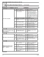
Unit does not operate.

1.

Freezer unplugged.

1. Plug in freezer.

2.

Fuse or breaker blown at 

main disconnect.

2. Make sure your freezer is 

connected to a separate 

circuit independent from any 

other electrical equipment. 

Have technician check fuse 

or breaker size and check for 

low voltage; if not within 10% 

of nameplate rating call power 

company.

3.

Actuator rod not installed.

3. Install actuator rod.

4.

Off on high pressure cut-out 

control.

4. Water turned off or defective 

water regulating valve. Check 

water supply. (Water Cooled)

5.

Circuit breaker tripped.

5. Reset. If trips again contact 

your Electro Freeze 

Distributor for service 

6.

Faulty selector switch.

6. Contact your Electro Freeze 

Distributor for service.

7.

Disconnected or broken wire 

in electrical circuit.

7. Contact your Electro Freeze 

Distributor for service.

Mix or water leaking from drain 

tube to drip tray.

1.

Damaged beater shaft seal 

or installed improperly.

1. Replace cup seal. Install 

properly.  

Mix leaking at dispensing head.

1.

Faulty head o-ring.

1. Replace o-ring.

2.

Head not properly installed.

2. Install head properly. Replace 

o-ring if pinched.

3.

Faulty Plunger o-ring or 

wrong o-ring in wrong o-ring 

grove.

3. Check the o-ring chart.

Dispensed product too soft. 

(Product temperature above 

28°F       [-2.2°C] )

1.

Dirty or blocked condenser, 

restricted air flow.

1. Unblock condenser or have 

cleaned by your Electro 

Freeze Distributor.

2.

Torque control not set firm 

enough.

2. Contact your Electro Freeze 

Distributor for service.

3.

Component failure.

3. Contact your Electro Freeze 

Distributor for service.

4.

Leak in refrigeration system 

resulting in little or no 

refrigeration.

4. Contact your Electro Freeze 

Distributor for service.

Summary of Contents for Arby's Electro Freeze Compact Series

Page 1: ...H C Duke Son LLC P N 185260 June 2017 Printed in U S A COMPACT SERIES SHAKE FREEZER Model CS704 185260 6 17 OPERATOR S MANUAL with Replacement Parts List...

Page 2: ......

Page 3: ...Operator s Manual for the Electro Freeze Model CS704 Compact Series Flavor Injected Shake Freezer All contents Copyright 2017 H C Duke Son LLC 2116 Eighth Avenue East Moline Illinois 61244 i...

Page 4: ...ety messages and the operating instructions in this manual DANGER The signal words DANGER WARNING and CAUTION are used with the safety alert symbol DANGER decals on the freezer may or may not have the...

Page 5: ...DO NOT attempt to repair the freezer until the main power supply has been disconnected Some freezers have more than one disconnect switch Contact your authorized service representative for original e...

Page 6: ...replace any label please contact your local authorized Electro Freeze Distributor or H C Duke Son LLC When ready to order you will need to determine the 1 part number 2 type of label 3 location of lab...

Page 7: ...ELECTRO FREEZE Shake Model CS704 Safety Decal Locations v 1 P N HC165126 2 P N HC165025...

Page 8: ...4 3 3 Reference Information 4 3 4 Installation Date 4 3 5 Dimensions 5 4 PART NAMES AND FUNCTIONS 6 5 OPERATOR CONTROLS INDICATORS 10 5 1 Rinse Switch 11 5 2 Spinner Motor Fuse 11 5 3 Lexible Spinner...

Page 9: ...PROCEDURES 26 9 1 Night or Idle Operation 26 9 1 1 General Cleaning 26 9 1 2 Operation 27 9 2 Draining Product From Freezer 28 10 PRODUCT INFORMATION 29 10 1 Overrun 29 10 2 Rerun 29 11 SYRUP FLAVOR...

Page 10: ......

Page 11: ...er products in this machine is considered misuse see Warranty This manual has been prepared to assist you in the proper operation and general maintenance of the Electro Freeze Model CS704 Freezer Your...

Page 12: ...the pallet 2 2 Installation 3 A minimum 3 inch 7 6 cm air space is required on both sides and back of the freezer for adequate ventilation 4 Test the operation of the head and flex shaft cover safety...

Page 13: ...connects to a NEMA 6 20R receptacle See Figure 2 1 3 Supply voltage must be within 10 of voltage indicated on the nameplate Request your local power company to correct any voltage problem 4 The contr...

Page 14: ...re 3 1 Fill in the following information as soon as you receive the Electro Freeze CS704 The item numbers encircled below correspond with the call out numbers in figure 4 1 1 Model Number ____________...

Page 15: ...ELECTRO FREEZE Shake Model CS704 185260 5 3 5 Dimensions Figure 3 2 Electro Freeze Model CS704 Dimensions...

Page 16: ...ELECTRO FREEZE Shake Model CS704 185260 6 4 Part Names and Functions Figure 4 1 Head Assembly 19 20...

Page 17: ...BER MIX Delivers syrup to the shake mix 10 O RING CHAMBER Prevents mix from leaking Lightly lubricate 11 HANDLE ASSY COMPLETE Opens and closes the plunger to start and stop the flow of product from th...

Page 18: ...m the freezing cylinder wall 3 SEAL CUP BEATER SHAFT Seals the opening between the freezing cylinder and the beater DO NOT LUBRICATE 4 WASHER SHAFT SEAL Holds the shaft seals together Must be lubricat...

Page 19: ...nd air into the freezing cylinder from the hopper 2 INSERT ASSEMBLY MIX FEED Regulator Regulates mix flow Open position for day operation and closed position for night 3 O RING INSERT ASSEMBLY Holds t...

Page 20: ...ce before the beater will operate continued 5 1 Syrup Pump Switch 1 This two position switch controls the operating mode of your freezer a ON right This position operates the syrup motor Always use th...

Page 21: ...EEZE position with water or sanitizer in the cylinder the freezer will be damaged c AUTO right This position activates both the beater motor and refrigeration unit This is the normal operating positio...

Page 22: ...Mix Float not shown 5 Operator Controls continued 5 8 Flavor Selection Buttons 8 These push buttons are used to select the flavor of shake to be dispensed Press the button for the desired flavor Selec...

Page 23: ...ndle used to clean mix chamber ports and syrup hoses 9 BEAKER 150 ML HC196109 Used in syrup calibration not shown 10 KIT O RING Contains all O rings and seals needing replacement on a regular basis no...

Page 24: ...ELECTRO FREEZE Shake Model CS704 185260 14 Figure 6 2 Dispense Head Assembly 6 2 Disassembly Instructions...

Page 25: ...tions continued 5 Remove the actuator rod 16 by lifting up and swing out 6 Hold onto the bottom of the dispense head 5 and release the mixer shaft 8 from the flexible spinner tube by lifting up the re...

Page 26: ...HAFT BEATER SEAL CUP BEATER SHAFT 11 Remove the beater bearing bushing figure 6 2 3 and beater shaft figure 6 3 from the cylinder Then remove the scraper blades 2 and shaft seal 3 4 from the beater sh...

Page 27: ...onsibility to be aware of and conform to the requirements for meeting federal state and local laws concerning the frequency of cleaning and sanitizing the freezer 1 Prepare a three compartment sink in...

Page 28: ...parts are washed rinse and place them in the sanitizing solution For proper sanitizing all parts must remain fully immersed in the sanitizer for 5 minutes Allow parts to air dry after sanitizing Impo...

Page 29: ...the cup seals 3 on the plastic washer 4 Apply a moderate amount of approved sanitary lubricant such as Compound 7 to the washer Do not allow any lubricant to come in contact with the bell shaped rubbe...

Page 30: ...ELECTRO FREEZE Shake Model CS704 185260 20 Figure 7 4 Head Assembly 7 Assembly continued...

Page 31: ...to the freezer by tilting the top of the head towards you aligning the studs with the holes in the head and sliding toward the freezer As you push the head towards the freezer carefully rock it into p...

Page 32: ...the o ring 3 on the mix feed insert 2 and lubricate Then install the o rings 4 on the mix feed tube 1 lightly lubricate Place the insert inside the mix feed tube 22 Lay the mix feed tube assembly in...

Page 33: ...d sanitize your hands and forearms 3 The mix feed tube assembly should be laying in the bottom of the hop per pan Do not install Important Never let the sanitizer remain in the freezer for more than 1...

Page 34: ...ispense head close the plunger 4 When the mix stops bubbling install the mix feed tube into the mix feed hopper drain in the open position Place the selector switch to the AUTO position and the syrup...

Page 35: ...hake dispenses 5 When cup is filled push handle up to stop dispensing and remove cup 8 2 Dispensing Milk Shakes Figure 8 3 CAUTION DO NOT touch or get too close to moving parts Clothing jewelry hair o...

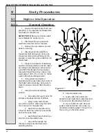
Page 36: ...he wash bottle with sanitizing solution 6 Using a brush and bottle of sanitizing solution wash down the bottom of the shake head and plunger being sure to clean the plunger spinner shaft hole with a b...

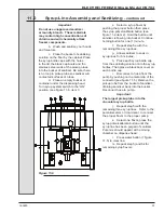
Page 37: ...1 2 Operation Look through top hole in tube you should see clear through Look through top hole in tube you should see the inner white plastic tube regulator blocking the opening Pin is in line with ho...

Page 38: ...Information Rerun 10 Pour 2 gallons of cold water into the hopper Place the selector switch to CLEAN and dispense the cold water Important DO NOT use hot water Damage to the freezer could occur 11 Fo...

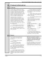
Page 39: ...eight e Use the following formula to figure overrun percentage Weight of liquid mix minus weight of frozen product divided by the frozen weight See example Example Weight of one pint of mix 18 oz Weig...

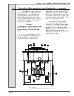
Page 40: ...metal clip of the connector see figure 11 1 Slowly pull the pickup tube out of the syrup bottle allowing the syrup from the tube and hose to drain back into the bottle Place the stainless steel picku...

Page 41: ...e syrup 8 Take a clean sanitized cloth and wash all soiled surfaces inside cabinet Disconnect the syrup and water lines from the mix chamber Remove the mix chamber and mixing shaft from the dispense h...

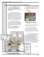
Page 42: ...he center of the pump head to fit into the pump drive housing mounted on the cabinet back wall turn until it snaps into place 3 Place the three 3 remaining pump heads on the mix pumps in the cabinet 4...

Page 43: ...see figure 11 4 item 2 Hold the button until sanitizer is flowing into bucket Continue holding button for one 1 minute f Repeat step 5e with the remaining three syrup lines g Allow sanitizer to soak i...

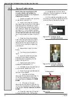
Page 44: ...5 Turn the syrup pump switch to OFF 6 Open the cabinet door to allow access to the four flavor adjustment potentiometers located above the mix pumps See figure 11 9 7 Approximate setting for the adjus...

Page 45: ...an and sanitize syrup lines with sanitizing solution 3 Clean the cylinder and drain tube with the appropriate brushes 3 Upon cleaning inspect and lubricate all seals and O rings as instructed that com...

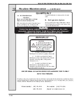
Page 46: ...stributor for service DO NOT place the freezer in service until the problem has been fixed MONTHLY B Test Flex Cover Switch The flex cover switch feature is designed to prevent the spinner shaft from...

Page 47: ...in this schedule or problems where service assistance is needed please call your local Distributor or H C Duke Son LLC Electro Freeze Service Department for factory service assistance Phone number 309...

Page 48: ...mix with a warm mild detergent solution Rinse in clear water and dry all parts thoroughly 3 Store the loose parts such as the head assembly beater assembly and pump parts in a safe dry place 4 Do not...

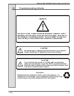
Page 49: ...HEN YOU SEE THIS SYMBOL BE ALERT TO THE POSSIBILITY OF PERSONAL INJURY DO NOT ATTEMPT TO CONTINUE UNTIL THE SAFETY PRECAUTIONS ARE THOROUGHLY UNDERSTOOD SAFETY CAUTION All maintenance adjustments must...

Page 50: ...Distributor for service 7 Disconnected or broken wire in electrical circuit 7 Contact your Electro Freeze Distributor for service Mix or water leaking from drain tube to drip tray 1 Damaged beater sh...

Page 51: ...fully closed 1 Close plunger completely 2 Starter or relay contact points stuck 2 Contact your Electro Freeze Distributor for service 3 Torque control not set properly or faulty 3 Contact your Electro...

Page 52: ...Dispensed product too hard 3 Mix feed tube not open 3 Check mix feed tube setting Compressor and beater motor operates only when dispensing 1 Defective torque control 1 Contact your Electro Freeze Dis...

Page 53: ......

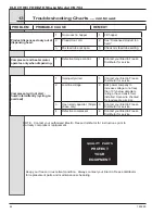
Page 54: ...Son LLC P N 185260 01 June 2017 Printed in U S A Quality Parts PROTECT YOUR EQUIPMENT Keep Your Freezer In Excellent Condition Always Contact Your Electro Freeze Distributor For Replacement Parts COM...

Page 55: ......

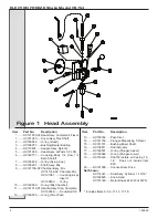
Page 56: ...your freezer when ordering parts parts may differ with a particular serial number of the same model Parts are listed using terminology that best fits the function of the part The illus trations in thi...

Page 57: ...61 Coupling Assy Insert 1 HC160650 O ring 10 HC160650 O ring Mix Chamber 11 HC121019 01 Handle Assy Disp Complete HC162629 Knob Ball 3 8 12 HC160555 O ring Pivot Post 13 HC135182 Post Pivot 14 HC14115...

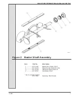
Page 58: ...re 2 Beater Shaft Assembly Item Part No Description 1 HC118708 Beater Assy Shake Short 2 HC140900 Blade Scraper Shake Non Rev 3 HC137593 Washer Double Shaft Seal 4 HC160557 Seal Beater Shaft Can be or...

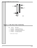
Page 59: ...Tube Assy Mix Feed 313 1 HC140721 Tube Mix Feed 313 Orifice 2 HC120664 Insert Assy Mix Feed Regulator 3 HC160611 O ring Insert Regulator 4 HC160621 O ring Mix Feed Tube Includes items 1 through 4 Figu...

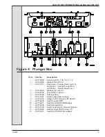
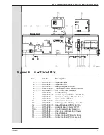
Page 60: ...Rod HC150456 Switch Snap Button 4 HC150452 Breaker Circuit 4 5A 5 HC150188 Timer DOB 5 60 Sec 6 HC150798 Terminal Strip 7 HC150381 Relay Flange Base w Cover 8 HC150343 Relay Control Flange 3PDT 24VAC...

Page 61: ...Plunger Rod 2 HC159973 Screw RDHM 6 32 x 2 Zn 3 HC141209 Guard Switch Assembly 4 HC137798 Insulator Switch 5 HC150456 Switch Snap Button 6 HC160393 Washer Flat 6 Brass 7 HC160199 Nut El Stop 6 32 ZN...

Page 62: ...150967 01 Control Speed 230VAC to DC Motor 8 HC120603 Board Assy Torque Monitor Shake 9 HC160743 Clamp Hose 3 1 6 to 4 10 IC574100349 Transformer Current 11 HC120095 Kit Recyle Timer Wiring Instructio...

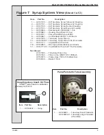
Page 63: ...ELECTRO FREEZE Shake Model CS704 185260 8 Figure 7 Syrup System View Sheet 1 of 2 VIEW FROM BACK SIDE OF HC121066 03 BACKET ASSY FLAVOR PUMPS...

Page 64: ...to DC Motor 9 HC121039 Tube Assy Syrup Pick up 10 HC121039 01 Tube Assy Syrup Pick up 3 8 Chocolate 11 HC141173 Cap Bottle Gal Punched 11A HC199050 Boot Syrup Bottle Black not shown 12 HC141173 01 Ca...

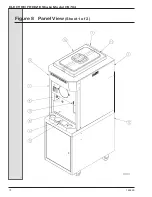
Page 65: ...ELECTRO FREEZE Shake Model CS704 185260 10 Figure 8 Panel View Sheet 1 of 2...

Page 66: ...62200 11 Latch CS Cart Not Shown HC161300 Switch Level Float Sensor HC161301 Float Level Sensor HC139230 Deflector Panel Left side Figure 8 Panel View Sheet 1 of 2 Hardware for Panels Panel Screw Nut...

Page 67: ...ELECTRO FREEZE Shake Model CS704 185260 12 Figure 9 Side View Sheet 1 of 2...

Page 68: ...and HC150244 Capacitor Run HC151414 Capacitor Start HC155063 Drier Filter 3 cu in Sweat HC151478 Grommet Comp Mtg HC151474 Relay Compressor Start HC151479 Sleeve Comp Mtg 2 HC155490 Valve Automatic E...

Page 69: ...4 HC153026 Stamping Main 5 HC160105 Nut Hex 5 16 18 ZN 6 HC160142 Washer Lock 5 16 ZN 7 HC160415 Bolt Carriage 5 16 18 x 3 ZN 8 HC140824 Shaft Drive 9 HC153614 Sheave Driven 10 HC160056 Screw SK Set...

Page 70: ...16 inch with 36 inch Handle HC184291 Chart O ring Laminated HC121061 Coupling Assy Insert 1 4 Flow 1 8 NPT Used in Calibration Process includes HC160632 O ring HC158051 Cup Overrun Measuring 1 Pint Us...

Page 71: ...ELECTRO FREEZE Shake Model CS704 185260 16 ELECTRO FREEZE Shake Model CS704 16...

Reviews: