background image

ELECTRO FREEZE Soft Serve Model GEN-5099

185242 


5

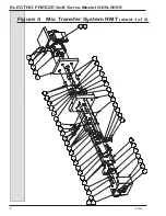
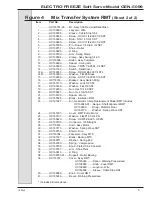
Figure 4 

Mix Transfer System RMT

 (Sheet 2 of  2)

Item 

Part No. 

Description

 * ..............HC118751-03.......Mt - Assy Cab Red Line/Relief Bisn

 1 .............HC138890............Lanyard - Wire

 2 .............HC160508............Sleeve - Cable Stop 3/64

 3 .............HC160464............Screw - HXHC 1/4-20X2 1/2 SST

 4 .............HC160386............Stud - 5/16-18 X 3/4 SST

 5 .............HC160465............Screw - HXHC 1/4-20X3 1/2 SST

 6 .............HC160338............Pin - Dowel 1/4 Dia X 3/4 SST

 7 .............HC139751............Shoe - Roller

 8 .............HC160628............O Ring

 9 .............HC138799............Arm - Swing Clamp

 10 ...........HC120504............Clamp - Assy Swing 1/4-20

 11 ............HC116009............Roller - Assy Complete

 12 ...........HC138800............Spacer - Swing Arm

 13 ...........HC160093............Screw - TRPS 1/4-28X2-1/4 SST

 14 ...........HC161302............Switch - Slide/Cover

 14A .........HC160357............Screw - RDHM #4-40X1/4 STL

 14B .........HC160393............Washer - Flat #6 Brass

 15 ...........HC159939............Screw - HXSF 1/4-20X11/16 SST

 16 ...........HC118763............Bracket - Assy Switch Mntg

 17 ...........HC160170............Washer - Lock 3/8 SST

 18 ...........HC160169............Washer - Flat 3/8 SST

 19 ...........HC159933............Nut - Hxsf 1/4-20 SST

 20 ...........HC159927............Nut - Hex 3/8-16 SST

 21 ...........HC138793............Spacer - Motor

 22 ...........HC165524............Block - Insulation RMT

 23 ...........HC121027............Kit - Gearmotor 1/6Hp Replacement Model RMT Includes:


    HC139046-01....Gauge - Shaft Alignment RMT


    HC139839.........Strap - Mt Motor Rear


    HC160173.........Washer - Spring Wave SST

 24 ...........HC141607............Cover - RMT Pump Motor

 25 ...........HC160137............Washer - Flat #10 X 3/4 ZN

 26 ...........HC160420............Screw - HXWF #8-32 X 3/8 ZN

 27 ...........HC150706............Connector - 3/8 Straight

 28 ...........HC118833............Cord - Assy Motor

 29 ...........HC160173............Washer - Spring Wave SST

 30 ...........HC139756............Shield - Drip

 31 ...........HC118764............Faceplate - Assy MTS

 32 ...........HC191527............Blank - Backup MTS

 33 ...........HC140711............Washer - Spring End

 34 ...........HC162330............Spring - Compression

 35 ...........HC140706............Knob - Fluted 1/4-20 Custom

 36 ...........HC138797............Arm - Shoe Pivot

 37 ...........HC160612............O Ring

 38 ...........HC138783-01.......Support - Roller Bearing

 39 ...........HC118767............Cover - Assy RMT


     HC165246.........Decal - Warning Pressurized


     HC138889.........Knob - Cover RMT


     HC138890.........Lanyard - Wire


     HC160508.........Sleeve - Cable Stop 3/64

 40 ...........HC138889............Knob - Cover RMT

 41 ...........HC165246............Decal - Warning Pressurized

  *  Includes all items above.

Summary of Contents for Electro Freeze GENESIS GEN-5099

Page 1: ...H C Duke Son LLC P N 185242 November 2016 Printed In U S A OPERATOR S MANUAL with Illustrated Parts List Soft Serve Freezer Model GEN 5099 185242 11 16...

Page 2: ......

Page 3: ...185242 iii All contents Copyright 2016 H C Duke Son LLC 2116 Eighth Avenue East Moline Illinois 61244 Operator s Manual for Electro Freeze Soft Serve Freezer Model GEN 5099...

Page 4: ...ssages and the operating instructions in this manual DANGER The signal words DANGER WARNING and CAUTION are used with the safety alert symbol DANGER decals on the freezer may or may not have the safet...

Page 5: ...to repair the freezer until the main power supply has been disconnected Some freezers have more than one disconnect switch Contact your IDQ authorized service representative or H C Duke Son LLC Servi...

Page 6: ...ed Electro Freeze Distributor or H C Duke Son LLC When ready to order you will need to determine the 1 part number 2 type of label 3 location of label and 4 quantity required and include a return ship...

Page 7: ...Model GEN 5099 185242 vii Safety Decal Locations HC165025 1 3 2 HC165246 HC165126 4 HC165048 Pressurized system Depressurize unit before dismantling mix transfer system Do not operate with cover remo...

Page 8: ...cal Requirements 3 2 4 Electrical Connections 4 3 Specifications 5 3 1 Particulars 5 3 2 Data Plate 6 3 3 Reference Information 6 3 4 Installation Date 6 3 5 Dimensions 7 3 6 WEEE Waste Electrical Ele...

Page 9: ...oting Tables 44 Replacement Parts Table of Contents iii Figure 1 Head Assembly 1 Figure 2 Beater Shaft Assembly 2 Figure 3 MTS RMT Hose Assembly 3 Figure 4 Mix Transfer System RMT 4 Figure 5 Cabinet P...

Page 10: ......

Page 11: ...oduce soft serve ice cream ice milk yogurt and similar frozen dairy products with a product serving temperature range of 15 to 25 F 9 to 4 C If such products are prepared from powdered concentrate the...

Page 12: ...nsit If the SHOCKWATCH label indicates red and or the carton is broken torn or punctured note the damage on the carrier s freight bill and notify the carrier s local agent immediately 1 Remove the car...

Page 13: ...ssure must be between 35 140 psig 241 965kPa for proper operation 5 Water cooled and air cooled remote freezers require at least 12 inches 30 cm above the top panel be free of obstructions Anything bl...

Page 14: ...the junction box located mid level behind the left side panel 5 Use a flexible connection when permissible All materials and connections must conform to local codes and the National Electrical Code 6...

Page 15: ...0 BTUH 2 2 kw Motor 3 2 kw Cooling Compressor Cabinet 1 1 6 HP 650 BTUH 125w Motor 190kw Cooling Beater Motor 2 HP 1 5 kw Refrigerant 404a Charge 3 75 lb 1 7 kg Mix Container 2 24 Qts 22 7 Liters Cyli...

Page 16: ..._________ 2 Serial Number ________________ 3 Electrical Spec Voltage _________ Phase _______ Hertz __________ 4 Maximum Fuse Size ____________ 5 Minimum Circuit Ampacity _______ 3 2 Data Plate Figure...

Page 17: ...conformity with EU 2002 96 EC this freezer at the end of life cycle is not to be discarded with normal urban waste Instead it is the user s responsibility to dispose of this product by returning it t...

Page 18: ...ELECTRO FREEZE Soft Serve Model GEN 5099 8 185242 4 Part Names and Functions...

Page 19: ...r and provides an opening for product to be dispensed 2 O RING PLUNGER Seals the plunger in the dispense head Must be lubricated to seal and slide properly 3 O RING HEAD Seals the dispense head to the...

Page 20: ...ELECTRO FREEZE Soft Serve Model GEN 5099 10 185242 4 Part Names and Functions continued Figure 4 2 Beater Shaft Assembly...

Page 21: ...G CYLINDER Holds the beater in place at the front of the cylinder Must be lubricated 3 BLADE SCRAPER Scrapes the frozen product from the freezing cylinder wall 4 O RING SHAFT SEAL Seals the beater sha...

Page 22: ...em MTS AIR METER TUBE AIR RETAINER AIR TUBE CLAMP SOFT HOSE HOSE MIX BRAIDED SUPPORT ROLLER BEARING HOSE TRANSFER RED LINE ROLLER ASSY COMPLETE SHOE ROLLER CLAMP SOFT HOSE O RING PORT AIR MIX INLET CL...

Page 23: ...ix transfer hose Squeezes transfer hose against rollers 3 ROLLER ASSEMBLY COMPLETE Squeezes mix air through tubing to freezing cylinder 4 KNOB HAND Locks roller shoe in position 5 ARM SWING CLAMP Swin...

Page 24: ...in place before the freezer will operate 1 Function Buttons Four Pressing any of these buttons will activate the icon directly above in the display screen Left side L1 L2 Right Side R1 R2 2 OFF Key Wh...

Page 25: ...ill activate and reduce product refrigeration The freezer will automatically cycle to maintain temperatures in the cylinder and cabinet below 41 F and keep product from deteriorating Use this position...

Page 26: ...to move the curser up or down to the desired sub menu Once the desired menu is highlighted in this example we will use Basic Settings press the select button to enter the sub menu Product Type and Tem...

Page 27: ...look at logged events i e power switch cycle low mix etc The log will display the last 50 events with the newest event at the top Error Log Allows the operator to look at logged errors i e Barrel ref...

Page 28: ...Shown Freeze Mode Y or N Clean Mode Y or N Standby Mode Y or N Cab Only Mode Y or N Cones Left 5 Screen Settings Operator can turn on or off the following functions Display Cabinet Temperature Y or N...

Page 29: ...etting LEFT RIGHT OFF OFF Press to start Left Clean Mode Press to start Right Clean Mode CABINET ON 370 F LEFT RIGHT OFF OFF CABINET ON 37 0 F PUMP ON OFF PUMP ON OFF BEATER ON OFF BEATER ON OFF Press...

Page 30: ...ection 9 Closing Procedures 9 1 Draining Product 5 Remove the spigot switch rods and open the spigots completely 6 Inside the refrigerated cabinet remove the MTS cover loosen the shoe clamp hand knob...

Page 31: ...long used to clean the disassembled shaft seal and bushing 5 HC158037 BRUSH 1 4 inch diameter 18 1 2 inches overall length used to clean the air meter hose the small hole in the back of the dispense...

Page 32: ...d swinging the bottom out and down Remove hand knobs 11 and pull the dispensing head 1 straight out 3 Remove the bushings and beater shafts from the cylinders 4 Remove scraper blades and shaft seal fr...

Page 33: ...e plastic washer on the shaft seal assembly 10 Remove mix containers covers and low mix probes 11 Remove the MTS cover 12 Remove MTS hose assemblies from the Mix Transfer Systems as follows figure 6 4...

Page 34: ...ter shaft cup seals plastic washers and O rings The plunger O ring grooves and nozzles as shown in figure 7 7 d The air bleed plug O ring grooves NOTE It is your responsibility to be aware of and conf...

Page 35: ...itizing 4 Using a warm dish detergent solution thoroughly brush the mix feed tubes from the refrigerated cabinet to the cylinders as shown in figure 6 9 the inside of the cylinders including the back...

Page 36: ...ry thoroughly 3 Brush in between rollers Flush clean with water bottle Important Do not let shoe sit in sanitizing solution or water Corrosion will occur in bore 4 Lubricate the shoe pivot arm and the...

Page 37: ...ubricant such as Petrol Gel to the O ring and the face of the plastic washer opposite the bell portion of the seal Do not allow any lubricant to come into contact with the bell shaped rubber portion o...

Page 38: ...der bushing and place on the end of the beater shaft Important ALWAYS make sure the cylinder bushing is positioned on the beater shaft properly Operating the freezer with a missing or badly worn bushi...

Page 39: ...rt Then slide a clamp over the hose to secure it to the port Finger tighten only The thumbscrew must lie parallel to the mix air inlet port 13 Slide another clamp over the mix transfer hose and connec...

Page 40: ...is facing out The line should be in the same position at the inlet and outlet guides of the roller bearing support as shown in figure 8 7 20 Swing the shoe over hose and tighten the swing clamp hand...

Page 41: ...UBE AIR RETAINER AIR TUBE CLAMP SOFT HOSE HOSE MIX BRAIDED SUPPORT ROLLER BEARING HOSE TRANSFER RED LINE ROLLER ASSY COMPLETE SHOE ROLLER CLAMP SOFT HOSE O RING PORT AIR MIX INLET CLIP TUBE RETAINER C...

Page 42: ...he mix tank in the refrigerated cabinet Fill with sanitizing solution Important Never let the sanitizer remain in the freezer for more than 15 minutes 5 Immerse the pickup tubes into the sanitizer sol...

Page 43: ...ff 13 After the cylinders are pressurized and the MTS has cycled off approximately 30 seconds Press the left and right Freeze keys 14 Allow the freezer to cycle for 15 minutes The product is now ready...

Page 44: ...anitized container 5 Mix must be handled according to local health codes 6 Place a clean sanitized container under the dispensing head 7 Very slowly open the side spigots and dispense the semi frozen...

Page 45: ...r bleed plugs up until they touch the bottom of the switch box Open the spigots 16 Turn the MTS pumps ON When sanitizer flows out the bottom of the head close the air bleed plugs and allow the MTS to...

Page 46: ...uct To correctly measure the overrun perform the following steps a Place an empty pint container on the scale and adjust your scale to zero b Remove container from scale and fill with liquid product t...

Page 47: ...e After the machine has run long enough to dispense at least one full cylinder of product you will have the overrun that the machine will hold the remainder of the day Contact your mix supplier for th...

Page 48: ...ny seal O ring and hose that is worn torn or loose fitting 4 Wipe all exterior surfaces of the freezer to remove any splattered mix 5 Check overrun and temperature of the product AS NEEDED CAUTION To...

Page 49: ...tizer f Wipe all surfaces with a clean dry cloth g Remove and clean shoe See figure 11 1 WEEKLY 1 Carefully inspect all parts for wear including seals O rings mix transfer tubes and blades 2 Replace a...

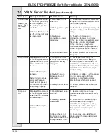
Page 50: ...hed and the rear drive coupling is rotating and the display does not read HEAD SWITCH Freezer has a head switch or software problem Turn the power switch OFF DO NOT place the freezer in service until...

Page 51: ...are in the OFF position 2 Remove the MTS cover to expose the roller assembly 3 Turn MTS switch to ON 4 Look at the MTS rollers they should NOT be rotating If they are rotating turn OFF mix switch and...

Page 52: ...ll your Electro Freeze Distributor to check water cooled condensers and flush clean to remove scale and deposits if necessary SEMI ANNUALLY 1 Have the condenser fan motor checked by your Electro Freez...

Page 53: ...in clear water and air dry all parts thoroughly 3 Store the loose parts such as the head assembly beater assembly and MTS parts in a safe dry place 4 Do not lay heavy objects on the plastic or rubber...

Page 54: ...ing Tables CAUTION All maintenance adjustments must be done by an Electro Freeze Distributor or authorized service technician Important Some refrigerants are hazardous to the earth s atmosphere To pro...

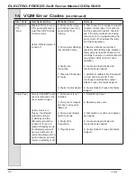
Page 55: ...tro Freeze Distributor for service 7 Faulty selector switch 7 Contact your Electro Freeze Distributor for service 8 Disconnected or broken wire in electrical circuit 8 Contact your Electro Freeze Dist...

Page 56: ...tch electrically or mechanically stuck closed Unit runs all the time 3 Contact your Electro Freeze Distributor for service 4 Component failure 4 Contact your Electro Freeze Distributor for service 5 L...

Page 57: ...sembly is not installed 1 Install head assembly 2 Magnetic head switch defective 2 Contact your Electro Freeze Distributor for service 3 Component failure 3 Contact your Electro Freeze Distributor for...

Page 58: ...stributor for service 2 Cabinet solenoid defective does not open 2 Contact your Electro Freeze Distributor for service 3 Cabinet switch defective 3 Contact your Electro Freeze Distributor for service...

Page 59: ...ontact your Electro Freeze Distributor for service 7 Motor defective or internal overload tripped 7 Contact your Electro Freeze Distributor for service MTS will not shut off 1 Hose broken 1 Replace ho...

Page 60: ...etween pickup tube and hose 2 Replace as needed 3 Air line hose cracked sucking air 3 Replace air line hose 4 Defective or missing duckbill valve 4 Replace valve Mix shoots out air meter 1 Swing Clamp...

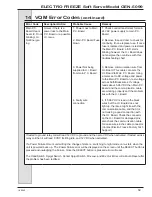
Page 61: ...ng the test cable does not resolve the issue then the main control board is not functioning properly and needs to be replaced Contact Electro Freeze Factory Tech Support NO Comm The U I Board is not r...

Page 62: ...g voltage ohm out coil windings If coil is not receiving voltage check relay responsible for activating coil and repair as needed If this condition exists a LOW PSI error code may also trip 5 Check Co...

Page 63: ...ctions and proper operation and possible voltage drop ohm compressor windings to check for a short and proper winding resistance check compressor starting components for failure allow compressor prote...

Page 64: ...the unit to ensure it is within specification Check wire connections to the unit and compressor Check compressor contactor for proper operation and possible voltage drop ohm compressor windings to che...

Page 65: ...Faulty wire connection 4 Program Issue 1 Install Head assembly 2 Test head switch to see if circuit remains open with magnet in place remove and replace head switch as needed 3 Locate Faulty wire conn...

Page 66: ...ntinues to operate 1 System is Short on refrigerant 2 Solenoid valve not activating 3 Low pressure control is Faulty 4 Restriction is refrigeration system 5 Faulty wire connection 6 System component f...

Page 67: ...ned or changed If this condition is present contact the Electro Freeze Technical Support Line 4 Confirm High pressure control is faulty by installing manifold gauges to confirm high side pressure is b...

Page 68: ...talled 2 Spigot switch has failed in the closed position 3 Spigot Switch is out of adjustment 4 Plunger is sticking open 1 Install Spigot Push Rod and start system to see if error is eliminated 2 Repl...

Page 69: ...and Pressure relief has not opened check to ensure relief is functioning properly 1 Pump control relay is stuck closed causing pump motor to stay energized 2 Faulty Pressure transducer out of calibra...

Page 70: ...shorts are present Start unit and check operation 6 Locate and repair faulty wire connections as needed 7 Attempt to calibrate the Transducer to 0 psi and re test unit If unit continues to malfunctio...

Page 71: ...5 96 VDC then Main P C Board and the communication cable are working properly and the problem lies with the U I Board 4 If 5 96 VDC is read on the black wires but the U I Board does not light up the i...

Page 72: ...Distributor for instructions prior to warranty compressor replacement Keep your freezer in excellent condition always contact your Electro Freeze Distributor for replacement parts and maintenance sche...

Page 73: ...H C Duke Son LLC P N 185242 01 November 2016 Printed In U S A SOFT SERVE FREEZER Model GEN 5099 P N 185242 01 11 16 REPLACEMENT PARTS MANUAL with Illustrations...

Page 74: ......

Page 75: ...ction of the part The illustrations in this section will help you to find the correct part number and description Place your parts order through your local authorized Electro Freeze Distributor Table...

Page 76: ......

Page 77: ...HC138149 Plug Air Bleed 7 HC116089 Push Rod Assy Plunger Switch 8 HC138009 Plunger Dispense Center 9 HC160269 Pin Handle 10 HC110007 Handle Assy Dispense Side includes HC162629 Knob Ball 3 8 16 THD B...

Page 78: ...cription 1 HC196085 Bushing Cylinder 2 HC113467 Shaft Assy Beater 3 HC134966 Blade Scraper 4 HC160500 O ring Seal 5 HC133098 Washer Shaft Seal 6 HC160557 Seal Beater Shaft Items 4 5 6 can be ordered t...

Page 79: ...8765 Port Assy Inlet Mix Air 4 HC138170 02 Tube Air 7 in Hose 5 Meter Air Order by meter number 6 HC116065 Clamp Assy Soft Hose 5 8 7 HC116094 Hose Assy Mix Braided 8 HC199033 Boot Mix Tube Seal 9 HC1...

Page 80: ...Serve Model GEN 5099 4 185242 Figure 4 Mix Transfer System RMT sheet 1 of 2 3 4 5 6 7 8 9 10 11 12 13 14A 14B 15 17 18 19 20 19 21 26 25 24 23 22 21 19 29 30 20 18 17 31 32 41 40 39 3 38 37 36 33 34 3...

Page 81: ...Washer Flat 3 8 SST 19 HC159933 Nut Hxsf 1 4 20 SST 20 HC159927 Nut Hex 3 8 16 SST 21 HC138793 Spacer Motor 22 HC165524 Block Insulation RMT 23 HC121027 Kit Gearmotor 1 6Hp Replacement Model RMT Inclu...

Page 82: ...AB Redline See Explode View Fig 5 16 HC116065 Clamp Assy Soft Hose 5 8 17 HC150612 Switch Door Push Button 17A HC118597 Actuator Assy Door Switch 18 HC138170 02 Tube Air 7 1 2 in 19 HC116094 Hose Assy...

Page 83: ...104 Nut HEX 1 4 20 ZN 4 HC159965 Screw HXHM 1 4 20 x 2 1 2 ZN 5 HC162323 Spring Compression MWZN Includes all items above Item Part No Description 1 HC150029 Relay Compressor 2 HC160739 Clamp Hose 3 9...

Page 84: ...ELECTRO FREEZE Soft Serve Model GEN 5099 8 185242 Figure 8 Switch Box sheet 1 of 2 TOP VIEW 1 2 3 4 5 6 7 8 9 10 11 12 13 14 15 16 17 18 19 20 FRONT VIEW...

Page 85: ...HC150044 Relay Miniature DPDT 230V Au Contact 7 HC150098 Socket Miniature Relay DPDT 8 HC150166 Clip Miniature Relay Retaining 9 HC150038 Support 1 2 Circuit Board 10 HC151702 Board PC Relay 11 HC1501...

Page 86: ...nel Screw Nut Speed Spacer Nut Speed on Frame Channel Rear HC160048 HC160117 n a n a Dispense HC160076 HC159132 HC138456 n a Front HC160076 HC159132 n a HC159067 Rear HC160048 HC160114 HC138456 n a Si...

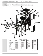
Page 87: ...p 24 Inch Black 11 HC114262 01 Shell Assy Door 24 In 12 HC141644 Trimstrip Lower 13 HC121518 Trimstrip Assy Upper 14 HC141649 Cover Electric Box 15 HC141642 Panel Dispense AC Air Cooled WC Water Coole...

Page 88: ...ELECTRO FREEZE Soft Serve Model GEN 5099 12 185242 Figure 11 Side Back View Breakdown...

Page 89: ...Condenser 26 HC155498 Drier Filter w Access 27 HC155459 Glass Sight 28 HC155141 Condenser Air AC 29 HC120446 Condenser Assy CAB Comp includes shroud hardware HC155139 Condenser Air 8x8 HC140662 Bracke...

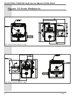
Page 90: ...ELECTRO FREEZE Soft Serve Model GEN 5099 14 185242 Figure 12 Gear Reducers HC153367 RH Gear Reducer 5 1 Ratio HC153366 LH Gear Reducer 5 1 Ratio...

Page 91: ...embly Item Part No Description 1 HC160320 Screw SKHC 10 24 x 1 3 4 SST 2 HC160166 Washer Lock 10 SST 3 HC160556 Gasket Mix Joint 4 HC139351 Collar Alignment 5 HC139349 Tube Mix Feed Clamp 6 HC139352 C...

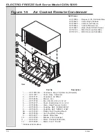
Page 92: ...Control 7 HC153420 Coupling Refr 3 8 MQC 3 8 SW 8 HC153418 Coupling Refr 1 2MQC 1 2 SW 8A HC153502 Flange Refr Coupling Mount 8B HC153503 Cap Dust Refr Coupling 9 HC139017 Shield Motor Rain 10 HC13763...

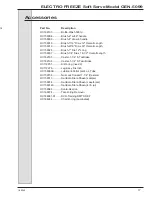
Page 93: ...HC158037 Brush 1 4 Dia x 18 1 2 Overall Length HC162105 Caster 1 1 4 ST w Brake HC162106 Caster 1 1 4 ST w o Brake HC119851 Kit O ring need 2 HC112978 Leg Assy Six Inch HC158000A Lubricant Petrol Gel...

Page 94: ......

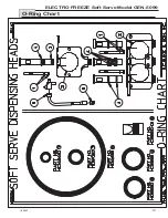
Page 95: ...ELECTRO FREEZE Soft Serve Model GEN 5099 185242 19 O Ring Chart...

Reviews: