14
CONTOIL
®
General
Meter configuration
CONTOIL
®
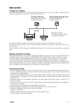
oil meters consist of a flow sensor and a measurement transducer with display, totaliser and signal outputs where applicable.
The flow rate range determines the nominal size of the flow sensor. The measurement transducer is either one complete ("universal") unit
(e.g. VZF) or is a combination of complementary units (transducer group) which can be chosen to suite a particular application (VZO).
Measurement transducer VZF / VZFA
Transducer group VZO / VZOA
with relay and analogue outputs
with RV pulser,
and electronic display
mechanical display
The flow sensor and the measurement transducer are calibrated jointly and form one metering unit.
For optimal results for differential measurements, meters of types VZFA or VZOA with special calibration should be used.
If the measurement transducer is replaced at a later stage, a certain divergence in measured values is to be expected.
Applications, planning and installation
CONTOIL
®
oil meters must only be used for their intended purpose and comply with safety regulations.
IBE
devices are manufac-
tured according to valid standards and guidelines.
IBE
guarantees the quality of the product in the context of its General Terms of
Business. The owner or operator will be liable for the correct installation as well as the appropriate handling of the equipment upon its re-
ceipt. The instructions for assembly and operation are to be followed exactly. None of the information stated here releases planners, in-
stallers and operators from their own careful and comprehensive assessment of the respective plant configuration in terms of functional
capability and operational safety.
Safety precautions
• The design of the plant must ensure that the meter cannot be damaged, especially from the effects of icing, torsion in the piping,
excessive heat expansion of the piping, misaligned pipes during installation, intrusion of foreign bodies or silt-up.
• The clearance distance of the piping must be adhered to when mounting the meter. If using flanged connections, the correct number of
connector elements must be fitted and they must be tightened with the correct torque in accordance with the screw manufacturer’s
instructions.
• Comply with the permissible operating data as defined on the type plate. Pressure test with a maximum of 1.5 x the nominal
pressure (PN).
• Make sure that no hazardous fumes can build up in the piping and in the meter during commissioning, decommissioning and
dismantling.
• The meter must at all times be completely filled with liquid during operation.
• Check the meter periodically for tightness of the connections and for proper functioning.
• If work is to be done on the installation, before each intervention:
a) release the pressure in the installation
b) if hazardous liquids are used, wear protective clothing and safety goggles
c) place a collecting tray underneath the installation.
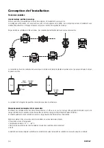
Schematic view. For details, see
the Dimensional Drawings section.
Flow sensor


