background image

Radio installation:

1

Use the supplied hook and loop
self-adhesive tape to secure your


chosen receiver to the inside 

of 

the 

radio compartment. We recommend


that you now setup your radio and 
the servo throws etc.

WARNING:

DO NOT INSTALL THE PROPELLER ONTO YOUR PLANE UNTIL THE RADIO SETUP HAS BEEN 

COMPLETED. ALSO, ALWAYS TURN YOUR TX ON FIRST AND ENSURE THAT THE THROTTLE 

STICK IS IN THE LOW POSITION BEFORE PLUGGING IN YOUR FLIGHT BATTERY TO THE 

ESC. THEN WHEN YOU HAVE FINISHED FLYING OR SETTING UP ALWAYS UNPLUG THE 

FLIGHT BATTERY FIRST BEFORE SWITCHING OFF YOUR TX.

NOTE:

For binding your radio, and for setting up the servo reverse, subtrims, and end point adjustments, etc, 
please consult your R/C instruction manual.

1

2

3

4

5

Repeat this process for all the other control surfaces.

Switch on your TX, then connect your flight battery to the ESC power cable with the


XT60 

connector.
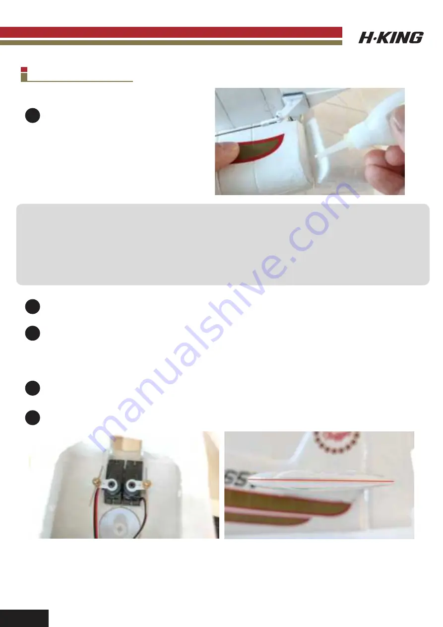
Elevator control surfaces setup: First set the servo trimmer on your TX radio to 

the 

center 

position.


Then loosen the stopper screw and ensure the servo horn is perpendicular to the 

pushrod as


shown. Secondly, ensure that the elevator control surface is perfectly level. Apply a 

drop of


Loctite glue to the thread of the stopper screw and hand tighten.

Finally, move the elevator control stick on your TX to check that it moves freely with no binding.


Once you are happy with this then set the end points to the recommended throws below.

7

Summary of Contents for Hellcat Little Nugget

Page 1: ...INSTRUCTION MANUAL Pl ease read t hi s m anualcaref ul l y bef ore operat i ng t hi s pl ane H Kings 990mm span Plug Fly sports scale F6F hot rod...

Page 2: ...subject to interference from sources outside of your control Interference may result in a momentary loss of control so it is always recommended that this product be used in a suitable open outdoors sp...

Page 3: ...tic performance on the same prop ESC and 4S battery This is only for those that can handle the extra speed and the extra rotational torque on hand launching INTRODUCTION FEATURES SPECIFICATION Up to 1...

Page 4: ...Stabilizer 2 Fuselage 3 Main wing 4 Horizontal stabilizer 5 Machine screw M3 x 40 mm 6 Nylon wing bolt 7 Hook and Loop double sided tape 8 8 x 6 Prop and prop hub adapter nut 5 2 H Kings 990mm span P...

Page 5: ...ess the horizontal stabilizer lightly against the rear of the seating area so as to leave a mark on the foam Make a 1mm wide groove with a hobby knife in the foam to allow for clearance of the elevato...

Page 6: ...the pre cut hinge slot in the rudder as shown Note Take extra care here to avoid breaking the foam hinge on the rudder as you gently slide the bottom hinge into the slot Secure the complete empennage...

Page 7: ...dder check that the rudder moves freely with no binding as the glue dries 6 Connect the elevator pushrod to the control horn as shown using the supplied quick keeper 7 Connect the rudder pushrod to th...

Page 8: ...area as shown Canopy Installation 1 We have supplied 2 different style canopies for you so that you can choose which one to use according to your own personal preferences Apply some foam safe glue to...

Page 9: ...ting up the servo reverse subtrims and end point adjustments etc please consult your R C instruction manual 1 2 3 4 5 Repeat this process for all the other control surfaces Switch on your TX then conn...

Page 10: ...propeller and then screw on the spinner nut Insert a 2mm Allen Key or 2mm Tommy Bar through the hole in the spinner nut Hand tighten the spinner nut until the prop and the adapter are locked securely...

Page 11: ...9 Control set up and CG C of G is 62 68mm from the leading edge of the wing CG 62 68mm...

Page 12: ...ly to control inputs and that the direction of travel is correct Visually re check all your control surfaces airframe screws and motor mount are in working order Check the voltage of your transmitter...

Page 13: ...round begin to ease in a little more elevator to begin the flare process the process of raising the nose to reduce the forward speed of the airframe and touch down with the nose slightly raised whilst...

Page 14: ...ly 2 The servo is damaged 1 Make sure the servo leads are connected properly 2 Replace servo 1 Control surfaces not centered 2 CoG is not in the correct position 1 Adjust the trims on the transmitter...

Page 15: ...T6 Fuselage Set w Decals SKU 9898000031 0 Cowl w Decals SKU 898000033 0 Hatch Cover w Canopies SKU 9898000035 0 8x6 Propeller SKU 9898000052 0 Wing Set w Decals SKU 9898000030 0 Horizontal Stabilizer...

Page 16: ...utaba S FHSS FHSS 2 SKU 9295000020 0 Turnigy Graphene Panther 2200mAh 4S 75C Battery Pack SKU 9067000372 0 Turnigy Graphene 2200mAh 4S 45C Lipo Pack W XT60 SKU 9067000136 0 ZIPPY Compact 2200mAh 4s 60...

Page 17: ...SKU 9052000155 0 Turnigy Accucell S60 AC Charger SKU 9052000138 1 Foam Cure EPP and EPO Foam Glue 4 oz SKU 9117000006 0 UHU POR Glue SKU 9934000001 0 HobbyKing Super Glue CA 50g 1 7oz Medium SKU HC 5...

Page 18: ...UK REP EC REP APEX CE SPECIALISTS LIMITED 89 Princess Street Manchester M1 4HT UK APEX CE SPECIALISTS LIMITED Unit 3D North Point House North Point Business Park New Mallow Road Cork T23 AT2P Ireland...

Reviews: