background image

9

www.myhtec.com

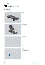
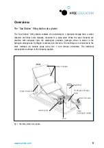
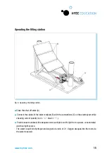
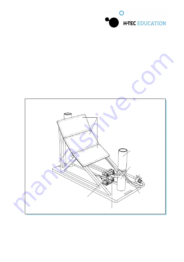
Fig. 1: The fi lling station at a glance

 Overview 

The "Gas Station" filling station at a glance

The “Gas Station” filling station consists of an 

electrolyzer

, a hydrogen storage tank, a water 

reservoir  and  three  solar  modules,  mounted  to  a  base  plate.  When  the  solar  modules  are 
provided  with  adequate  light,  the 

electrolyzer

  produces  hydrogen  which  is  stored  in  the 

hydrogen storage tank. Hydrogen is removed via the tube. The 

electrolyzer

 is connected to the 

solar  modules  via 

banana

  plugs  using  two  2  mm  female  connectors.  The  individual 

components are shown in the following graphic. 

Solar modules

Shut-o

  valve

Water reservoir

electrolyzer

Over

fl

 ow

Hydrogen storage 
tank

Tube
(hydrogen outlet)

Cap

Summary of Contents for Education D203

Page 1: ...Operating instructions D203 Fuel Cell Concept Car Gas Station...

Page 2: ...2 www myhtec com H TEC EDUCATION GmbH 1902 Pinon Dr Ste B College Station TX 77845 USA Phone 1 979 703 1925 Email info myhtec com Website www myhtec com...

Page 3: ...tents Introduction About these instructions Safety instructions Content Overview Starting up Operation Technical data Troubleshooting Shutting down Maintenance Transport and storage Disposal 04 05 05...

Page 4: ...for a more efficient energy supply while conserving natural resources as much as possible The hydrogen filling station Gas Station is used to generate and store hydrogen The car named the Fuel Cell C...

Page 5: ...rved This product may only be put into operation and operated under the direction of the supervi sor in charge Safetyinstructions Product specificsafetyinstructions The product may only be used Accord...

Page 6: ...6 www myhtec com tube with shut off valve Content filling station car overflow...

Page 7: ...7 www myhtec com transport box with insert optional water bottle companion book operating instructions general safety instructions...

Page 8: ...8 www myhtec com...

Page 9: ...e plate When the solar modules are provided with adequate light the electrolyzer produces hydrogen which is stored in the hydrogen storage tank Hydrogen is removed via the tube The electrolyzer is con...

Page 10: ...r breathing fuel cell stack and a hydrogen storage tank mounted to a vehicle base plate The car can be operated when it is supplied with hydrogen via the hydrogen storage tank The individual component...

Page 11: ...Assemble the filling station as shown in figure 3 Attach the overflow to the hydrogen storage tank using a clockwise motion Attach the tube to the connection on the hydrogen storage tank Do not yet co...

Page 12: ...as shown in figure 4 Fill the hydrogen storage tank up to the mark with distilled water 2 S cm as shown in figure 4 Briefly open the cap on the electrolyzer until a small amount of water comes out of...

Page 13: ...r may cause injuries Before starting up ensure correct polarity of the connecting cables and the electrical connections red black Do not touch the diode CAUTION Risk of injury from hot surfaces The su...

Page 14: ...t or sustain irreparable damage if it is too close to the lamp Observe the minimum distance defined by the manufacturer when operating solar modules with lamps CAUTION Risk of damage due to improper h...

Page 15: ...nsuring correct polarity red black Provide solar modules with adequate direct sunlight or with light from a power concentrated electrical light source The water is split into hydrogen and oxygen at a...

Page 16: ...side to the hydrogen side This may cause the water level to rise on the hydrogen side and fall on the oxygen side check and if necessary adjust the water level regularly during operation To this end t...

Page 17: ...the overflow of the filling station s hydrogen storage tank has completely dropped The hydrogen is now inside the hydrogen storage tank of the car 6 Close the cap on the fuel cell stack 7 Close the sh...

Page 18: ...ctrolyzer Number of cells 1 Active surface per cell 17 mm x 17 mm Operating medium distilled water 2 S cm Permissible operating voltage 0 2 V DC Permissible operating current 0 1 5 A Rated power consu...

Page 19: ...cell Number of cells 2 Active surface per cell 20 mm x 20 mm Operating media hydrogen and atmospheric oxygen from air Open circuit voltage Max 2V DC Short circuit current Max 650 mA Rated power output...

Page 20: ...erformance Solution Dry the fuel cell by opening and blowing out the connections CAUTION Risk of damage due to compressed air The use of compressed air for drying the fuel cell may cause irreparable d...

Page 21: ...Possible cause 2 The overflow tank is not secured firmly in place Solution Secure the overflow tank firmly in place Despite correct setup the electrolyzer or the fuel cell is not working Possible caus...

Page 22: ...rfl ow Drain the hydrogen storage tank and the water reservoir as shown in fi gure 7 The water must be disposed of correctly e g drain Before putting the product into storage observe the following poi...

Page 23: ...om shock and vibrations Transport and storage Disposal Do not dispose of fuel cells and electrolyzers as general household waste WARNING Risk of re due to catalytic substances The catalysts for the el...

Page 24: ...H TEC Education 2019 No part of this guide may be reproduced in whole or in part in any manner without the express written permission of H TEC Education Subject to technical changes...

Reviews:

Related manuals for Education D203