


2
OPERATION STEPS
:
1
、
Put machine in a steady position
,
and then check whether the power is
suitable to motor voltage. Turn on the electricity supply and examine
whether the revolution of main shaft follows the arrows. If not
,
turn off the
power and switch the two wire lines.
2
、
Adjust the working table to a lower or higher position according to the
diameter of material.
3
、
Change and adjustness of the sand belt
:
(
1
)
Press the rod of sand belt in the direction of clockwise
【
Fig 1-A
】
and
then you can change the sand belt. After that, move the adjusting rod back.
Note: After the start of machine, keep away from lifting up the adjusting rod
to prevent danger.
(
2
)
Adjust the screw
【
Fig 1-B
】
for pulling out-in the sand belt. The sand
belt should be aimed at the center of wheel.
A
B
Fig 1
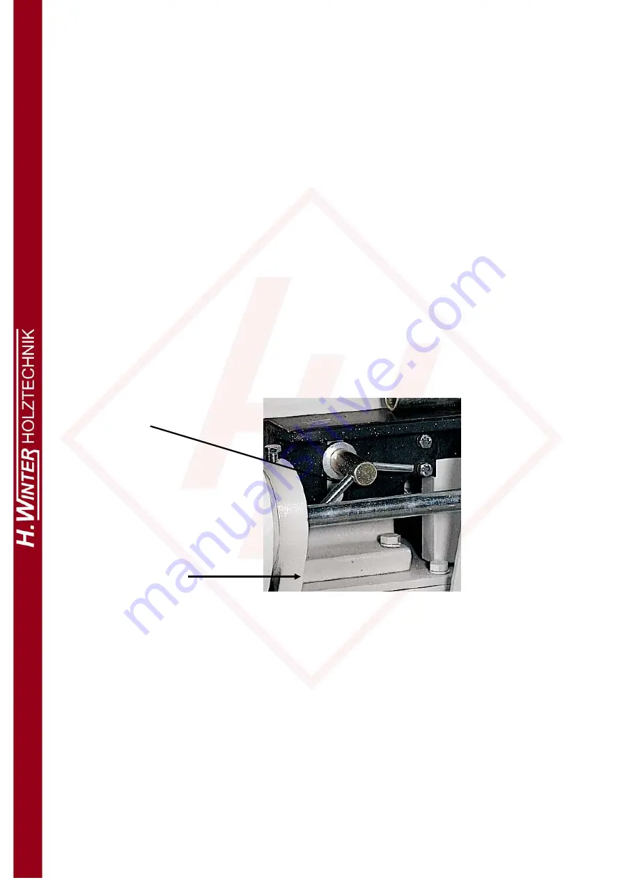
4
、
The suitable pressure for pressing wheel is to keep the thinkness of
material less than 1M/M.
The adjustment procedure
:
Loose the nut
【
Fig 2-A
】
and adjust the screw
【
Fig 2-B
】
according to the
pressure and then lock nut
【
Fig 2-A
】
.


