Current Limit Adjustment Procedure
Adjustment of the current limit requires a few special tools:
•
Multimeter
•
Small Screwdriver
To adjust the current limit, follow this procedure:
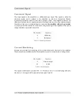
1. Connect the multimeter to the terminals shown in (connector J1).
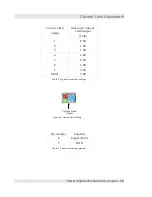
2. Adjust the trimpot to the desired voltage for the required current setting shown in Table
8, or follow the relationship of Equation 1.
Status Indicator LEDs
Status indication provides a visual means of determining the operating state of the
amplifier. The amplifier is provided with a thermal shutdown feature to prevent damage to
the amplifier. Indication of the status is provided by means of two LEDs and a secondary
output, the Fault Indicator output on pins 15 and 16 of the User Connection Header. The
indicator LEDs are green and red.
The flashing condition of the red LED indicates that the amplifier is entering thermal
shutdown. This situation typically occurs when the amplifier is driving large loads, or the
amplifier is inadequately cooled. The amplifier will continue to operate, but the output will
be temporarily shutdown during this interval.
External Fault Indication
The state of the red LED is duplicated on the fault output of the User Connection Header,
on pins 15 (signal) and 16 (GND). The output is current limited with a 200 ohm resistor,
30
Power Amplifier Module User's Guide
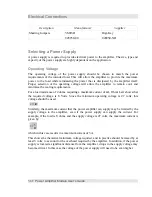
Figure 13. Amplifier status indicator LEDs.
Green – Power good, amplifier ready.
Flashing – entering thermal shutdown
Thermal shutdown
Amplifier disabled
Power supply fault


