background image

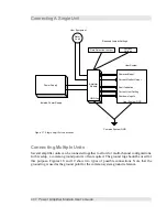
Connecting A Single Unit

Connecting Multiple Units

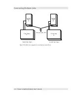
Several amplifier units can be connected together to allow for multi-channel configurations.
In this setup, a common ground point is often required. The ground lug should be used for
this purpose. Figures 18 and 19 show two types of possible connections. Note that the
ground lug is used as the ground point for the common system ground reference.

40


Š

  Power Amplifier Module User's Guide

Figure 17. Single amplifier connections.

Power Supply

Amplifier

Module

Motor/

Load

Command Input

Current Monitor Output

Fault Indication

Shutdown Inputs

Current Limit Setting

Gain Selection Jumper

Current/

Voltage

User System

GND Lug

User System GND

Isolated Power Supply

Common System GND

Required Jumper Settings

User Equipment

Summary of Contents for LPAM-1

Page 1: ...Linear Power Amplifier Module User s Guide Version 2 0 ...

Page 2: ...on 18 Power Supply 23 Load Connection 25 GND Lug 26 Offset Adjustment 26 Offset Adjustment Procedure 27 Current Limit Adjustment 27 Current Limit Adjustment Procedure 29 Status Indicator LEDs 29 External Fault Indication 30 Amplifier Enable Inputs 30 Command Signal 31 Current Monitoring 32 Installation 33 Mechanical Mounting 33 Cooling Fans 34 Determining the Dissipated Power 35 Determining the Re...

Page 3: ...Table of Contents Connecting Multiple Units 41 Appendix A 45 Dimensions 45 ii ...

Page 4: ...r adjustable values 23 Figure 8 Power connection details 24 Figure 9 Load connection details 25 Figure 10 GND connection 26 Figure 11 Offset adjustment 27 Figure 12 Current limit setting 29 Figure 13 Amplifier status indicator LEDs 30 Figure 14 Mounting hole locations A green or B blue 33 Figure 15 Mounting locations for the small twin fans 34 Figure 16 Mounting location of the large fan 35 Figure...

Page 5: ... gain in current mode 18 Table 4 Factory configuration of the integration components 18 Table 5 Power supply connection 24 Table 6 Amplifier output terminals 25 Table 7 Ground lug connection 26 Table 8 Typical current limit settings 28 Table 9 Current limit output pinouts 29 Table 10 Amplifier enable truth table 31 Table 11 Command signal pinouts 31 Table 12 Current output pins 32 iv ...

Page 6: ...put Startup Shutdown Circuitry disables the amplifier until power supplies stabilize Applications Voice Coil Actuators X Y Stages Robotics Magnetic Bearings Description The Quanser Power Amplifier is a linear power amplifier designed to drive loads in either voltage mode or current mode In the current mode configuration the amplifier is best suited for inductive loads such as dc motors and voice c...

Page 7: ......

Page 8: ...V Operating Temperature ambient temperature natural convection cooling Power de rating occurs beyond this temperature 50 C Amplifier Specifications Parameter min max typical Units Power Supply Range 27 60 30 V Input Voltage Differential max Supply voltage 27 V Supply voltage 48 V 20 40 V V Input Impedance 1 MOhm Output Impedance 0 2 Ohms Bandwidth Voltage Mode Current Mode 10 10 kHz kHz Power Ampl...

Page 9: ...el 0V 1 1 mA mA Amplifier Fault output TTL compatible with 200 ohm resistor inline current limited to 25 mA 0 5 V Current Sense output buffered 1 mA Current Limit Output reference voltage 0 5 V A 0 5 V A Offset Adjust Adjusts output to zero for zero command input signal 8 Power Amplifier Module User s Guide ...

Page 10: ...ng connections and when locating functions on the board Power Amplifier Module User s Guide 9 Figure 1 Layout of the amplifier board and the various features Ground Lug Power Load Connection Voltage Current Select Integrator Reset Enable Power Supply Monitor Enable Current Limit Adjust Offset Adjust Amplifier Configuration Block Fault Status Indicator LEDs User Connection Header ...

Page 11: ......

Page 12: ... connectors Improper connections may result in poor performance or may possibly damage the amplifier and other connected equipment User Connection Header The user connection header is where the user will make the connections to the amplifier The command signal and the feedback signal current measurement are present on this header Power Amplifier Module User s Guide 11 ...

Page 13: ...ed Do not make connections to this terminal 9 Current Monitor Current measurement output 0 5V A 10 GND Ground connection 11 ENABLE Amplifier Enable input This line must be at 0V for the amplifier to operate 12 GND Ground connection 13 ENABLE Amplifier Enable input This line must be at 5V for the amplifier to operate 14 5V Available for signal conditioning circuitry 10mA max 15 FAULT OUTPUT Fault i...

Page 14: ... load at increased current driving capability up to a maximum of 7A continuous output In voltage mode the commanded signal will correspond to an output voltage related by the gain setting of the amplifier For example with a gain setting of 1 a 1 volt input signal will produce a 1 volt output signal at the output terminals of the amplifier Similarly with a gain setting of 4 a 1 volt command would p...

Page 15: ...nals is automatically adjusted by the amplifier to provided the commanded current For this reason care must be taken to ensure that the amplifier is being asked to do something that it can accomplish based on the available power supply The maximum current that the amplifier can provide is limited by the supply voltage and the impedance of the load Power Supply Monitor Enable The power amplifier em...

Page 16: ...ration is with the jumper in the 1 2 position enabling the integrator reset feature Amplifier Configuration Block The amplifier configuration block allows customization of the amplifier to the user s needs These customizable features include gain setting amplifier tuning These features allow the user to customize the amplifier to suit a specific application Table 2 provides a description of the co...

Page 17: ...n can be calculated as the product of G1 G2 GF where GF is the final gain stage of the amplifier and is fixed to a value of 20 GT G1 G2 G F It is important to note that when choosing resistor values to set the gains G1 and G2 that the values chosen do not cause the amplifier to saturate This means that the gains used must keep the voltages below 11 volts 16 Power Amplifier Module User s Guide Figu...

Page 18: ...nt loop error feedback integration capacitor 22nF F C9 Current loop feedback compensation capacitor typically use factory value of 2 2nF 2 2nF G Do not make connections in this position open H This enables the integrator clearing circuitry and must be installed for it to function properly short Table 2 Details of the various configuration options Power Amplifier Module User s Guide 17 Figure 6 Sch...

Page 19: ... gain in current mode The bolded text shows the factory configuration Tuning the Amplifier In current mode the amplifier must be tuned to the load inductance and resistance This is important to optimize its performance for the load The tuning components as configured at the factory are Component Purpose Value Units E Integration gain capacitor 2 20E 008 Farads B Loop gain resistor 1000 Ohms Table ...

Page 20: ...oop externally It is recommended that you first try with an integrator and adjust the offset to zero If the motor runs away in open loop with the expected load then you may want to completely eliminate the integrator by shorting component E The drawback of removing the integrator is that the forward gain will now be load dependent The expected forward gain with an integrator is G 2 D A With no int...

Page 21: ...oportional loop gain Kp instead since the gain reaches unity as Kp gets larger For example setting Kp 10 using a 10K resistor for B will result in the following Kp 10 B 10 K R Load Gain 2 0 9804 4 0 9615 6 0 9434 8 0 9259 10 0 9091 which shows that the gain is closer to unity even with load resistance changes This gain however may result in undesired ringing if the load inductance is too low Imple...

Page 22: ...e oscilloscope probe to the current sensor measurement Apply a small amplitude 1KHz square wave about 100 mV p p make sure the commanded amplitude does not saturate the amplifier or blow the load Start with no integration i e short components E or replace it with a large capacitor e g 2 microfarad Observe the step response of the system and tune as follows If the response is too slow increase the ...

Page 23: ...nd and will limit the practical bandwidth of the system Preliminary tuning may be performed using the MATLAB script or the Simulink simulation supplied with the system as described below Using the MATLAB Script You need to have MATLAB for this Simply run the file current_amp_design m from MATLAB This will display a step response and a frequency response and print the theoretical small signal bandw...

Page 24: ...ulink Model A Simulink model is also available Open the model current_amp_i_c mdl Run the MATLAB script current_amp_params m Run the simulation and open the two scopes to observe the current step response Tune the Load resistance and inductance to your desired response Note that the Simulink model takes into account the non linearity introduced by amplifier voltage limits as well as other dynamic ...

Page 25: ...wer supply should be a floating type supply and not referenced to ground on the secondary The amplifier employs an under voltage lockout system to disable the amplifier in the event that the supply voltage falls below 27 volts This feature may be disabled by removing the jumper J2 RESET EN from the 1 2 position and placing it in the 2 3 position Note that this action will disable the power up powe...

Page 26: ...ing capability User connections should make use of all the pins for optimal current handling ability The output of the amplifier is floating It is not referenced to ground Pin Number Function 1 Motor 2 Motor 3 Motor 4 Motor Table 6 Amplifier output terminals Power Amplifier Module User s Guide 25 Figure 8 Power connection details Pin Signal 1 Positive 2 Negative Pin 1 ...

Page 27: ...d be treated as common between the input output signals and the amplifier itself Do not use the negative GND power input to the amplifier as a ground reference or damage to the amplifier and or your equipment may result Pin Number Function 1 Virtual Ground Reference GND Table 7 Ground lug connection 26 Power Amplifier Module User s Guide Figure 9 Load connection details Pin Signal 1 Load 2 Load 3 ...

Page 28: ... amplifier to zero follow the procedure shown below 1 Command a zero input to the amplifier or short the command input pins together remove the input connections to prevent damaging the signal source 2 Connect a multimeter to the output terminals of the amplifier 3 Adjust the potentiometer until the meter reading displays zero 0 0V 4 The output of the amplifier should now provide zero voltage curr...

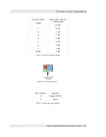
Page 29: ... potentiometer clockwise increases the current limit setting while turning it counter clockwise will decrease the current limit setting The voltage at the Current Limit Output pins 6 and 7 on the User Connection Header should be measured for accurate determination of the maximum current setting A meter can be connected to these two pins to measure the current limit setting The output signal varies...

Page 30: ...t Volts 1 0 50 2 1 00 3 1 50 4 2 00 5 2 50 6 3 00 7 3 50 MAX 5 00 Table 8 Typical current limit settings Pin Number Function 6 Signal 0 5V 7 GND Table 9 Current limit output pinouts Power Amplifier Module User s Guide 29 Figure 12 Current limit setting Current Limit Adjust ...

Page 31: ...a secondary output the Fault Indicator output on pins 15 and 16 of the User Connection Header The indicator LEDs are green and red The flashing condition of the red LED indicates that the amplifier is entering thermal shutdown This situation typically occurs when the amplifier is driving large loads or the amplifier is inadequately cooled The amplifier will continue to operate but the output will ...

Page 32: ...are ANDed together to determine the logical state Table below shows the truth table for these connections ENABLE ENABLE Amplifier Status 0V 0V Disabled 0V 5V Disabled 5V 5V Disabled 5V 0V ENABLED Table 10 Amplifier enable truth table The ENABLE input is tied to 5V through a 4 99k ohm resistor The ENABLE input is tied to GND 0V through a 1k ohm resistor This default configuration leaves the amplifi...

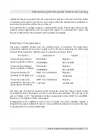
Page 33: ...oper ground line should be connected to the ground lug of the amplifier if the system design mandates a grounded connection Pin Number Function 4 Reference 5 Reference Table 11 Command signal pinouts Current Monitoring Outputs are provided for monitoring of the current delivered to the load by the amplifier These outputs are available whether the amplifier is used in current mode or voltage mode P...

Page 34: ...the amplifier Proper mounting of the amplifier will also help cooling and prolong the service life of the amplifier A cooler amplifier runs better and will perform better over the long term The surface that the amplifier is mounted to can aid in the cooling of the amplifier Care should be taken to ensure that the amplifier is not exposed to excessive moisture or used in areas were metal debris may...

Page 35: ...ld be paid to the direction of airflow Airflow should be flowing towards the surface of the heatsink Determination of the proper CFM rating for the selected fan depends highly on the application and the enclosure of the amplifier Note that the mounting surface of the amplifier may contribute to the total effective cooling area This may greatly reduce the airflow requirements of a fan The maximum p...

Page 36: ... the power dissipated is given by any of the following P D 2 Iload V supply V output P D 2 V output Rload V supply V output P D 2 Iload V supply Iload Rload The second and third equations are obtained by substituting Ohm s law for the required parameter Power dissipated PD is given in Watts This power will be given off as excess heat in the amplifier and must be removed by natural convection or th...

Page 37: ...f heat in Watts that must be dissipated The constant in the equations is obtained from the density of air 1 29 kg m3 and the specific heat of air 930 J kg C The constant is then adjusted to provide results in the units desired Example Rload 1 ohm Vsupply 27 volts Iload max 5 amps P D 2 Iload V supply Iload Rload PD 220 Watts If we allow the temperature of the amplifier to increase 20 C then we hav...

Page 38: ...w Description Manufacturer Supplier Connector plug terminal block 2 position 3 50mm Weidmuller 1638780000 Digi Key 281 1018 ND Connector plug terminal block 4 position 3 500mm Weidmuller 1638800000 Digi Key 281 1020 ND Connector housing 16 positions 0 100 single row AMP Tyco Electronics 2 87499 9 Digi Key A3025 ND Connector socket pins 22 26AWG crimp type 16 pins required maximum AMP Tyco Electron...

Page 39: ...f 2 ohms requiring a maximum current of 4A Ohm s Law shows that the required voltage is 8 Volts Since the minimum operating voltage is 27 volts this voltage should be used v iR Similarly the maximum current that the power amplifier can supply may be limited by the supply voltage to the amplifier even if the power supply can supply the current For example if the load is 8 ohms and the supply voltag...

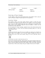
Page 40: ...r requirements are met almost any type of supply can be used One important note is that isolated power supplies only should be used Off line type switching supplies that have the secondary common with the primary may damage the amplifier and prove dangerous Only isolated secondary type power supplies should be used with the power amplifier module Connecting A Single Unit A single amplifier can be ...

Page 41: ...f possible connections Note that the ground lug is used as the ground point for the common system ground reference 40 Power Amplifier Module User s Guide Figure 17 Single amplifier connections Power Supply Amplifier Module Motor Load Command Input Current Monitor Output Fault Indication Shutdown Inputs Current Limit Setting Gain Selection Jumper Current Voltage User System GND Lug User System GND ...

Page 42: ...Units Power Amplifier Module User s Guide 41 Figure 18 Multiple amplifiers connected with a single power supply Power Supply Amplifier Module 1 Amplifier Module 2 Isolated Power Supply Amplifier Module n Common System GND ...

Page 43: ...wer Amplifier Module User s Guide Figure 19 Multiple power supplies to drive multiple power amplifiers Power Supply 1 Amplifier Module 1 Amplifier Module 2 Isolated Power Supply Power Supply 2 Isolated Power Supply Common System GND ...

Page 44: ...ensions The following pages show the mechanical drawings for the heatsink of the power amplifier module These drawings can be used in the fabrication of the enclosure of a mounting fixture Power Amplifier Module User s Guide 43 ...

Page 45: ...Dimensions 44 Power Amplifier Module User s Guide ...

Reviews: