background image

Installation Manual 
H3C SecPath F100-A Firewall 

Chapter 7  MIM Modules


7-1


Chapter 7  MIM Modules 

7.1  MIM Options 

Currently the H3C SecPath F100-A firewall supports these types of multifunctional 
interface modules (MIMs):  

z


1-port 10Base-T/100Base-TX FE interface module (1FE)  

z


2-port 10Base-T/100Base-TX FE interface module (2FE) 

z


4-port 10Base-T/100Base-TX FE interface module (4FE) 

z


High-performance network data encryption module (HNDE)  

7.2  Installing and Removing an MIM 


  Caution: 

There is a shield finger on the front panel of the MIM module, which provides 
electromagnetic shielding for the firewall. You must keep the shield finger intact when 
replacing the module. Do not remove the shield finger.  


Before installing MIMs, read Chapter 2  “Installation Preparations” carefully. 

I. Tools 

ESD-preventive wrist strap 

II. Installing an MIM 


  Caution: 

Before performing any of the following operations, make sure you have completely 
powered down the firewall to avoid getting electric shocks. 


Step 1: Place the firewall with its front panel facing you. 

Step 2: Turn off the site power and remove the power cord. 

Summary of Contents for A -

Page 1: ...H3C SecPath F100 A Firewall Installation Manual Hangzhou H3C Technologies Co Ltd http www h3c com Manual Version T2 08044B 20070622 C 1 03...

Page 2: ...InnoVision and HUASAN are trademarks of Hangzhou H3C Technologies Co Ltd All other trademarks that may be mentioned in this manual are the property of their respective owners Notice The information i...

Page 3: ...ity Products Web Based Configuration Manual It directs users to configure the H3C SecPath Series Firewalls in Web mode Organization H3C SecPath F100 A Firewall Installation Manual is organized as foll...

Page 4: ...in braces and separated by vertical bars One is selected x y Optional alternative items are grouped in square brackets and separated by vertical bars One or none is selected x y Alternative items are...

Page 5: ...er operation may cause bodily injury Caution Means reader be careful Improper operation may cause data loss or damage to equipment Note Means a complementary description Environmental Protection This...

Page 6: ...Rack 2 3 2 2 Safety Precautions 2 3 2 3 Unpacking Inspections 2 4 2 4 Installation Tools Meters and Equipment 2 4 Chapter 3 Firewall Installation 3 1 3 1 Installation Flow 3 1 3 2 Mounting the Firewal...

Page 7: ...5 13 Chapter 6 Troubleshooting 6 1 6 1 Troubleshooting PSU 6 1 6 2 Troubleshooting Configuration System 6 1 6 3 Troubleshooting Application Upgrading 6 2 Chapter 7 MIM Modules 7 1 7 1 MIM Options 7 1...

Page 8: ...on 4 2 Figure 4 3 Select connection port 4 2 Figure 4 4 Define port parameters 4 3 Figure 4 5 Select emulation type 4 4 Figure 5 1 Send File dialog box 5 3 Figure 5 2 Sending File interface 5 4 Figure...

Page 9: ...5 Table 2 1 Temperature humidity requirements in the equipment room 2 1 Table 2 2 Limits on the dust particles in the equipment room 2 1 Table 2 3 Harmful gas limits in the equipment room 2 2 Table 3...

Page 10: ...networks constructed on the open Internet H3C SecPath F100 A firewall supports multiple virtual private network VPN services such as layer 2 tunneling protocol L2TP VPN IP security IPsec VPN generic...

Page 11: ...rnet z OSPF and RIP2 to offer MD5 authentication and guarantee reliable exchange of routing information z Virtual router redundancy protocol VRRP to provide communication line or equipment backup in c...

Page 12: ...xed LAN 1 interface LAN 1 10 Fixed LAN 2 interface LAN 2 11 Fixed LAN 3 interface LAN 3 12 Auxiliary port AUX 13 Console port CONSOLE 14 System LED SYS 15 Power LED PWR Figure 1 1 Front panel of the H...

Page 13: ...tores the communication data of the running system with the CPU 1 2 3 LEDs Table 1 2 LEDs on the H3C SecPath F100 A firewall LED Description PWR Power supply unit PSU LED OFF means the PSU is not supp...

Page 14: ...inal Connected to the serial interface of a local PC running terminal emulation software Command line interface CLI II AUX port Table 1 4 Attributes of the AUX port Item Description Connector RJ 45 In...

Page 15: ...ath F100 A Firewall Chapter 1 Product Overview 1 6 Item Description Interface type Both LAN and WAN interfaces support auto MDI MDIX Frame format Ethernet_II Ethernet_SNAP Operating mode 10 100 Mbps a...

Page 16: ...semiconductor CMOS circuitry to fail Table 2 1 lists the temperature and humidity requirements Table 2 1 Temperature humidity requirements in the equipment room Temperature Relative humidity 0 C to 4...

Page 17: ...ent room is dust proof z Maintain adequate temperature and humidity z Wear an ESD preventive wrist strap and clothes when contacting the circuit board z Place the removed circuit board upward on the E...

Page 18: ...ate ventilation inside the chassis z The rack has a good ventilation system z The rack is stable enough to support the weight of the device and the installation accessories z The rack is well grounded...

Page 19: ...ur agent for shortage or wrong delivery 2 4 Installation Tools Meters and Equipment I Tools z Phillips screwdriver z ESD preventive wrist strap z Static shielding bag II Cables z Grounding wire and po...

Page 20: ...ice to the specified location Connect PGND wire Connect power cord Connect the device to console terminal Check Power on Power off and disconnect the power cord Install MIM optional Connect device to...

Page 21: ...tuff on the firewall 3 2 2 Rack Mounting The H3C SecPath F100 A firewall is designed to be mounted in 19 inch standard racks Table 3 1 shows its physical dimensions Table 3 1 Physical dimensions of th...

Page 22: ...all provides a grounding screw which must be well grounded so as to safely conduct the inductive and leaky current to the earth ground and thereby improve the capability of the whole device to guard a...

Page 23: ...of the firewall at the other end is a DB9 female connector which can be plugged to the serial interface of the console terminal Figure 3 3 illustrates a console cable A A X3 Figure 3 3 Console cable...

Page 24: ...LAN0 LAN1 LAN2 and LAN3 on the firewall correspond to E0 0 E0 1 E0 2 and E0 3 interfaces in the command line respectively by executing the undo insulate command in system view you can configure the f...

Page 25: ...to 240 VAC 50 Hz or 60 Hz Figure 1 2 shows the power socket on an AC powered model II Recommended AC power socket You are recommended to use a single phase three terminal socket with an earth contact...

Page 26: ...l during installation verify that z Enough clearance has been reserved around the ventilation openings of the device and the workbench rack is stable enough z Proper power supply is used z The PGND wi...

Page 27: ...of the console cable to the console port on the firewall and the DB9 connector to the serial interface on the PC see Figure 4 1 RS 232 serial interface Console cable PC H3C SecPath F100 A Console por...

Page 28: ...ows98 as an example 1 Select connection port Select the serial interface to be used from the Connect Using drop down list The serial interface selected here must be the one connected to the console ca...

Page 29: ...arity None z Stop bit 1 z Flow control None Click OK and the HyperTerminal dialog box appears Figure 4 4 Define port parameters 3 Select emulation type Choose Properties Settings to enter the correspo...

Page 30: ...correctly connected z The voltage of the power supply matches the requirements z The console cable is correctly connected The console terminal or PC has been started and the associated parameters have...

Page 31: ...t H3C appears the system is ready for your configuration 4 1 3 Booting Process After being powered up the firewall first runs the Boot ROM program The terminal screen displays the following system inf...

Page 32: ...guration Fundamentals 4 2 1 Basic Configuration Procedures Following are the basic steps that you can follow to configure the firewall Step 1 Figure out detailed networking requirements including netw...

Page 33: ...ch as tracert and ping z Have detailed debugging information for troubleshooting your network z Enter the conflict free keyword portion instead of the whole command because the CLI supports command pr...

Page 34: ...ts Press Ctrl B to enter Boot menu Then the system displays Please input Boot ROM password Caution z Press Ctrl B within three seconds to access the Boot menu after the prompt Press Ctrl B to Enter Bo...

Page 35: ...d Extended Segment of Boot ROM with XModem 3 Restore Extended Segment of Boot ROM from FLASH 4 Backup Extended Segment of Boot ROM to FLASH 5 Exit to Main Menu Enter your choice 1 5 The menu provides...

Page 36: ...ready Step 3 Change your terminals baud rate see Figure 4 4 to the same baud rate for software downloading 115200 bps in this example After that disconnect the terminal Dial in Disconnect reconnect i...

Page 37: ...tem file length 7868992 bytes http zip file length 921329 bytes Writing file flash system to FLASH Please wait it may take a long time Writing into Flash Succeeds Writing file flash http zip to FLASH...

Page 38: ...he extended segment of Boot ROM with XModem The subsequent operation steps are the same as those for upgrading the application program Caution This upgrade approach is used to upgrade only a portion o...

Page 39: ...lays Writing to Boot ROM Please wait Restoring Boot ROM program successed Step 3 When the Boot ROM operation menu appears again select 5 to exit and reboot the firewall 5 4 Upgrading the Application P...

Page 40: ...ver 192 168 1 10 IP address of the gateway 10 110 95 117 Caution z The upgrade should be performed through interface WAN2 on the firewall z The IP address of the server 192 168 1 10 field must be set...

Page 41: ...firewall offers FTP server function which provides you another way of updating configuration files and upgrading application and Boot ROM program You only need to connect a FTP client local or remote...

Page 42: ...3 24 FTP Client Router Ethernet interface 10 110 10 10 24 H3C SecPath F100 A FTP Server WAN PC 10 110 20 13 24 FTP Client Router Ethernet interface 10 110 10 10 24 H3C SecPath F100 A FTP Server WAN PC...

Page 43: ...access FTP server using this user name and password III Uploading downloading application configuration files and uploading Boot ROM program Step 1 Enter the path of the files or applications in DOS...

Page 44: ...delete unreserved command to permanently delete old version files or other files to save the memory space otherwise new files cannot be uploaded z After uploading Boot ROM program using the put comma...

Page 45: ...the firewall to change the Boot ROM password Start the firewall When System starts booting appears on the configuration terminal press Ctrl D and then the system prompts Please input Boot ROM passwor...

Page 46: ...ware upgrade but you still cannot operate successfully the system prompts invalid version At this time select this option to cancel the version checking for version upgrade However this option can fun...

Page 47: ...ked the above items contact the agent 6 2 Troubleshooting Configuration System If the firewall operates normally after being powered up the console terminal displays booting information if the system...

Page 48: ...these values 6 3 Troubleshooting Application Upgrading I Fault 1 1 Symptom Boot the firewall upgrade Comware software using TFTP and the system displays the following Net Port Download Menu 1 Change...

Page 49: ...aded files are not available z The paths of the files are not correct Confirm that the files to be downloaded are under the path specified by the TFTP server III Fault 3 1 Symptom Boot the firewall up...

Page 50: ...00 A Firewall Chapter 6 Troubleshooting 6 4 Note There is a bar code pasted on the firewall Since the bar code contains product and maintenance information you need to tell the agent about the informa...

Page 51: ...ling and Removing an MIM Caution There is a shield finger on the front panel of the MIM module which provides electromagnetic shielding for the firewall You must keep the shield finger intact when rep...

Page 52: ...tall the MIM II III Removing an MIM Step 1 Place the firewall with its front panel facing you Step 2 Turn off the site power and remove the power cord Step 3 Remove all interface cables from the front...

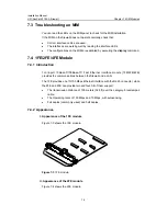
Page 53: ...troduction 1 2 4 port 10Base T 100Base TX Fast Ethernet interface module 1FE 2FE 4FE provides the communications between the firewall and a LAN The 1FE provides one 10 100 Mbps Ethernet interface with...

Page 54: ...4 3 Interface Attributes Table 7 1 shows the interface attributes of the 1FE 2FE and 4FE modules Table 7 1 Interface attributes of the 1FE 2FE and 4FE modules Attribute 1FE module 2FE module 4FE modu...

Page 55: ...on the 1FE 2FE 4FE module panel and how to read their state Table 7 2 LEDs on the 1FE 2FE 4FE module LED Description LINK OFF means no link is present ON means a link is present ACTIVE OFF means no p...

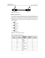
Page 56: ...ors of the outer insulator Usually a solid color wire and a white solid color wire are organized in pairs But sometimes wires are also paired by color coded points Pair 1 Blue White blue Pair 1 Orange...

Page 57: ...N switch z Crossover cable The sequences of the twisted pairs crimped in the RJ 45 connectors at both ends are different It connects a terminal device PC or router to another terminal device You make...

Page 58: ...ion of the IP packets featuring high performance and high reliability Insert HNDE module in the MIM slot of the SecPath Series Security Products The main board forwards the IP packets and implements t...

Page 59: ...mal operation of CPLD Complex Programmable Logic Device In these circumstances contact our agents for support 2 Symptom 2 The ACTIVE LED stays off when powering on the firewall Solution When powering...

Reviews: