1-9
S5800-32C
Front Panel
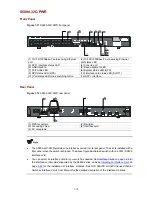
Figure 1-9
S5800-32C front panel
(1) 10/100/1000Base-T auto-sensing Ethernet
port
(2) 10/100/1000Base-T auto-sensing Ethernet
port status LED
(3) SFP+ interface status LED
(4) Console port
(5) USB interface
(6) Seven-segment LED
(7) Port mode LED
(8) System status LED (SYS)
(9) RPS status LED (RPS)
(10) Interface card status LED (SLOT1)
(11) Port status LED mode switching button
(12) SFP+ interface
Rear Panel
Figure 1-10
S5800-32C rear panel
(1) Bail latch
(2) RPS receptacle protective cover
(3) Grounding screw
(4) Interface card
(5) AC receptacle
z
The S5800-32C provides one interface card slot on its rear panel. The slot is installed with a filler
panel when the switch is shipped. The above figure illustrates a switch with one LSW1SP4P0
interface card.
z
You can select an interface card for your switch as needed. See
Interface Cards
on page
1-26
for
the interface card models supported by the S5800 series, and see
Installing an Interface Card
on
page
3-24
for the installation of interface modules. See
H3C S5820X & S5800 Series Ethernet
Switches Interface Cards User Manual
for the detailed description of the interface modules.


