29
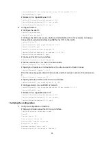
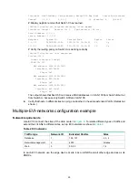
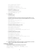
Interface Local Address Server Address Network ID Reg Auth Status Vpn-instance
Tunnel1 1.1.3.1 1.1.1.1 1 15 disabled E [No Vrf]
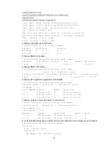
# Display neighbor entries that Switch C has learned.
[SwitchC] display evi neighbor-discovery client member
Interface: Tunnel1 Network ID: 1 Vpn-instance: [No Vrf]
Local Address: 1.1.3.1
Server Address: 1.1.1.1
Neighbor System ID Created Time Expire Status
1.1.1.1 000F-0001-0001 2013/01/01 12:12:12 13 Up
1.1.2.1 000F-0000-0002 2013/01/01 12:12:12 13 Up
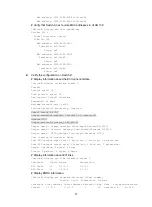
# Verify the routing policy on Switch A is working correctly.
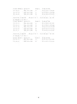
[SwitchC] display evi isis remote-mac
Process ID: 0
Tunnel interface: Tunnel1
VLAN ID: 100
MAC address: 0002-0100-0001
Interface: EVI-Link1
Flags: 0x2
MAC address: 0002-0100-0002
Interface: EVI-Link1
Flags: 0x2
MAC address: 0002-0100-0003
Interface: EVI-Link1
Flags: 0x2
The output shows that Switch C can receive MAC addresses in VLAN 100 from Switch B but not
from Switch A, because only Switch A filters VLAN 100.
4.
Verify that hosts in different sites can ping one another in the same extended VLAN. (Details not
shown.)
Multiple-EVI-networks configuration example
Network requirements
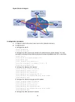
Use EVI to connect the sites of the data center in
. To isolate different types of traffic and
extend their VLANs to different sites, set up EVI networks as shown in
Table 2 EVI networks
Traffic type
Network ID
Extended VLANs
Sites
Database
1
100, 101
2, 3, 4
Network management
2
4000
All sites
Web
3
50, 80
1, 4
In each EVI network, use the edge device at site 4 as an ENDS and all other edge devices as its
ENDCs.

