Installation Manual
H3C S5500-SI Complete Series Ethernet Switches
Chapter 1 Product Overview
1-9
(1)
(10)
(2)
(3)
(4)
(5)
(6)
(7)
(9)
(8)
(1): 1000/100 Mbps SFP port LED
(2): 10/100/1000 Base-T autosensing Ethernet port LED
(3): Console port
(4): 7-segment digitron display
(5): System LED
(6): LED for power slot 1
(7): LED for power slot 2
(8): Mode LED
(9): Mode switching button
(10): Air intake vent
Figure 1-9
Front panel of the S5500-20TP-SI Ethernet switch
Note:
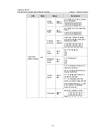
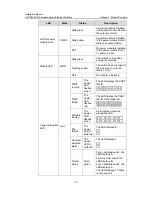
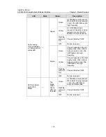
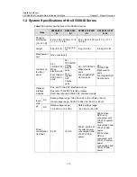
For details about LEDs on the front panel, refer to section 1.3.3 LEDs of
S5500-20TP-SI Switch.
II. Rear panel
(1)
(2)
(4)
(3)
(1): Grounding screw
(2): Power slot 1
(3): Power cable bail latch
(4): Power slot 2
Figure 1-10
Rear panel of the S5500-20TP-SI Ethernet switch
III. Power supply system
The S5500-20TP-SI Ethernet switch adopts AC input.
Rated voltage range: 100 VAC to 240 VAC, 50 Hz or 60 Hz
Input voltage range: 90 VAC to 264 VAC, 50 Hz or 60 Hz
IV. Cooling system
The S5500-20TP-SI Ethernet switch provides five fans (three for the system, and one
for each power module) for heat dissipation.


