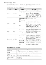
Manual Version
: 5W100-20090929
(5) Fasten the captive screws on the LSWM1WCM10 clockwise with the Philips screwdriver
until the LSWM1WCM10 is fixed into the chassis.
Removing the LSWM1WCM10
(1) Wear an ESD-preventive wrist strap, ensure a good skin contact and make sure that the
ESD-preventive wrist strap is properly grounded.
(2) Loosen the captive screws on the LSWM1WCM10 counterclockwise with the Philips
screwdriver until all spring pressure is released.
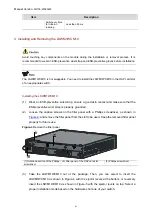
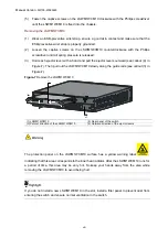
(3) Hold each ejector lever with a hand and pull the ejector levers outward (see callout (4) in
Figure-7). Then pull out the LSWM1WCM10 slowly along the guide rails (see callout (3) in
Figure-7
Remove the LSWM1WCM10
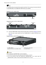
(1) LSWM1WCM10
(2) Rear panel of the switch
(3) Pull-out direction of the LSWM1WCM10
(4) Outward direction of the ejector levers
The protection panel on the LSWM1WCM10 surface has a yellow warning label
,
indicating that this area corresponds to the inner heat radiator. After the LSWM1WCM10 runs for
a period of time, this area may be very hot. So keep your hands away from the area while
removing the LSWM1WCM10 to avoid being hurt.
If you do not install a new LSWM1WCM10 in the slot, install a filler panel to prevent dust from
entering the switch and ensure normal ventilation in the switch.
viii


