background image


25 

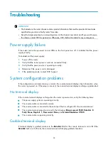
No response from the serial port 

If the serial port does not respond, verify that the serial cable is in good condition and the serial port 

settings are correct. 

Restoring the factory settings 

Scenario 1 

Symptom 

When you replace the router, the router password is lost. As a result, you cannot log in to the router 
and do not know the router configuration. 

Solution 

Because the router is replaced, you do not need to save the configuration of the router. In this case, 

you can press the 

Reset

 button for more than 4 seconds to reboot the router and restore the factory 

settings. Then, you can use the username and password shipped with the router to log in to the router. 
When the router configuration must be saved and you have a console cable, you can log in to the 

router from the BootWare menu. 

Scenario 2 

Symptom 

After the configuration is modified, the network connectivity is lost. When you check the configuration, 

the  configuration  is  very  complicated  and  it  is  hard  to  locate  the  errors.  In  this  case,  you  must 

configure the router again. 

Solution 

If you have not saved any configuration, you can reboot the router by pressing the 

Reset

 button for a 

short time or power off the router. 
If you have saved the configuration, delete the configuration file at the CLI, and press the 

Reset

 button 

to restore the factory settings. 

Scenario 3 

Symptom 

The router crashes. 

Solution 

Press the 

Reset

 button for a short time to reboot the router. 

Summary of Contents for MSR 800

Page 1: ...H3C MSR800 Routers Installation Guide New H3C Technologies Co Ltd http www h3c com hk Document version 6W102 20170608...

Page 2: ...r trademarks that may be mentioned in this manual are the property of their respective owners Notice The information in this document is subject to change without notice Every effort has been made in...

Page 3: ...that you replace with actual values Square brackets enclose syntax choices keywords or arguments that are optional x y Braces enclose a set of required syntax choices separated by vertical bars from w...

Page 4: ...ORTANT An alert that calls attention to essential information NOTE An alert that contains additional or supplementary information TIP An alert that provides helpful information Network topology icons...

Page 5: ...screenshots and other information in the examples differ from what you have on your device Obtaining documentation To access the most up to date H3C product documentation go to the H3C website at htt...

Page 6: ...ecting the console cable and setting terminal parameters 17 Setting console terminal parameters 18 Connecting the power adapter 20 Verifying the installation 21 Powering on the router 21 Startup proce...

Page 7: ...ii Appendix B LEDs 31 LEDs 31 MSR800 31 MSR800 W 31 MSR800 10 32 MSR800 10 W 32 LED description 33 Index 34...

Page 8: ...ause permanent eye damage Use a good grounding system This is essential for reliable operation Confirm that the resistance between the chassis and the ground is less than 1 ohm Site requirements The r...

Page 9: ...pplied with the router Prepare it yourself 2 Lock the wrist strap tight around your wrist to keep good contact with the skin 3 Insert the ESD plug into the ESD socket in the chassis 4 Attach the allig...

Page 10: ...eptacle is grounded correctly Install a lightning arrester at the input end of the power supply Installation accessories and tools Figure 1 and Figure 2 list the accessories and tools required for ins...

Page 11: ...possible Keep the router far away from radio transmitters radar and high frequency or high voltage devices Use electromagnetic shielding when necessary Lightning protection The grounding cable of the...

Page 12: ...n a mounting screw on the chassis cover intact and if you want to open the chassis contact H3C for permission Otherwise H3C shall not be liable for any consequence Installation prerequisites You have...

Page 13: ...6 Figure 3 Installation flowchart...

Page 14: ...ing the router on a wall position the router so the network interfaces face downwards and the sides with ventilation openings are perpendicular to the ground as shown in Figure 5 To mount the router o...

Page 15: ...rackets do not place objects on the router To install the router in a rack 1 Mark locations of the cage nuts on the front rack posts based on holes in the mounting brackets as shown in Figure 6 The mo...

Page 16: ...n rack posts as shown in Figure 7 a Insert one ear of a cage nut into the marked installation hole b Use a flathead screwdriver to push another ear into the same hole Figure 7 Installing cage nuts 3 I...

Page 17: ...o the rack Grounding the router WARNING Connecting the router grounding cable correctly is crucial for protecting the router from lightning and EMI Make sure the grounding resistance is less than 5 oh...

Page 18: ...ring with a blow dryer to completely cover the metal part Figure 10 Attaching the ring terminal Grounding the router through the rack 1 Make sure the rack has been correctly grounded 2 Remove the grou...

Page 19: ...12 Figure 11 Connecting the grounding cable to the router Figure 12 Grounding the router through the rack...

Page 20: ...is 2 Put the ring terminal of the grounding cable on the grounding screw 3 Use a screwdriver to fasten the grounding screw 4 Remove the nut from the post on the grounding strip 5 Use the needle nose p...

Page 21: ...o the earth to serve as a grounding conductor as shown in Figure 15 Figure 15 Grounding to a conductor buried in the earth Installing a WLAN antenna Only the MSR800 W and MSR800 10 W support the WLAN...

Page 22: ...an Ethernet port on the router 2 Connect the other end of the cable to the peer device 3 Examine the port LED status For more information see LED description Figure 17 Connecting the router to a compu...

Page 23: ...eer transceiver module 5 Power on the router and examine the port LED status For more information see LED description Figure 18 Connecting optical fibers to a fiber port NOTE Keep the connector on the...

Page 24: ...and then connect the RJ 45 connector of the console cable to the router console port To connect the console cable as shown in Figure 20 1 Select a console terminal which can be an ASCII terminal with...

Page 25: ...er the name of the new connection in the Name field and click OK Figure 21 Connection description 3 Select the serial port to be used from the Connect using list and click OK Figure 22 Setting the ser...

Page 26: ...tings click Restore Defaults Figure 23 Setting the serial port parameters 5 Select File Properties in the HyperTerminal window Figure 24 HyperTerminal window 6 On the Settings tab set the emulation to...

Page 27: ...to 240 VAC 50 Hz to 60 Hz DC Rated voltage 12 VDC To connect the power adapter as shown in Figure 26 1 Make sure the router is correctly grounded For more information see Grounding the router 2 Using...

Page 28: ...gured correctly on the console terminal Before starting up the router set up the console terminal as described in Connecting the console cable and setting terminal parameters Then power on the router...

Page 29: ...eed 533MHz Flash Size 128MB PCB Version 2 0 BootWare Validating Press Ctrl B to enter extended boot menu Starting to get the main application file flash msr800 cmw520 a2511 bin The main application fi...

Page 30: ...console terminal For more information see Startup process After completing the POST the system prompts you to press Enter When the command line prompt appears the router is ready to configure Configur...

Page 31: ...pport System configuration problems If the configuration environment setup is correct the console terminal displays boot information when the router is powered on If the setup is incorrect the console...

Page 32: ...word shipped with the router to log in to the router When the router configuration must be saved and you have a console cable you can log in to the router from the BootWare menu Scenario 2 Symptom Aft...

Page 33: ...the Reset button You can use the button to reboot the system or restore the factory settings 1 Press the Reset button for a short time to reboot the router 2 Press the Reset button for more than 4 sec...

Page 34: ...sis views The figures in this appendix are for illustration only MSR800 Figure 27 Front view 1 Power receptacle 2 GE LAN ports GE1 to GE4 3 GE WAN port GE0 4 GE WAN fiber port SFP0 5 Console port 6 Re...

Page 35: ...r port SFP0 5 Console port 6 Reset button 7 USB port Figure 30 Rear view 1 Grounding screw 2 WLAN antenna port 3 WLAN antenna port MSR800 10 Figure 31 Front view 1 Power receptacle 2 GE LAN ports GE2...

Page 36: ...W Figure 33 Front view 1 Power receptacle 2 GE LAN ports GE2 to GE9 3 GE WAN port GE0 4 GE WAN port GE1 5 GE WAN fiber port SFP1 6 Console port 7 Reset button 8 USB port Figure 34 Rear view 1 Groundi...

Page 37: ...Rated voltage of the AC power adapter 100 VAC to 240 VAC 50 Hz or 60 Hz 100 VAC to 240 VAC 50 Hz or 60 Hz 100 VAC to 240 VAC 50 Hz or 60 Hz 100 VAC to 240 VAC 50 Hz or 60 Hz Rated AC power 12 W 12 W...

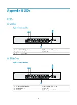
Page 38: ...status LED yellow 2 GE port status LED green 3 System status LED 4 VPN LED 5 Combo port status LED MSR800 W Figure 36 Front panel LEDs 1 GE port status LED yellow 2 GE port status LED green 3 System...

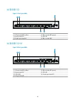
Page 39: ...tus LED green 3 System status LED 4 VPN LED 5 Combo port status LED 6 GE port status LED MSR800 10 W Figure 38 Front panel LEDs 1 GE port status LED yellow 2 GE port status LED green 3 System status L...

Page 40: ...he extended segment does not exist Steady yellow The system software image does not exist VPN LED Front panel Off No IPSec VPN tunnel is present Steady on A minimum of one IPSec VPN tunnel is present...

Page 41: ...n flowchart 5 Installation prerequisites 5 Installing the router 7 L LED description 33 LEDs 31 P Power supply failure 24 Powering on the router 21 Pre installation checklist 4 R Restoring the factory...

Reviews: