147
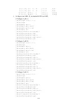
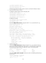
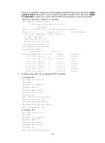
2.2.2.2/32 ISIS 15 10 2.1.1.2 Vlan1
3.1.1.0/24 ISIS 15 20 2.1.1.2 Vlan1
3.2.1.0/24 ISIS 15 20 2.1.1.2 Vlan1
3.3.1.0/24 ISIS 15 30 2.1.1.2 Vlan1
3.3.3.3/32 ISIS 15 20 2.1.1.2 Vlan1
4.1.1.0/24 ISIS 15 30 2.1.1.2 Vlan1
4.4.4.4/32 ISIS 15 30 2.1.1.2 Vlan1
5.5.5.5/32 ISIS 15 20 2.1.1.2 Vlan1
127.0.0.0/8 Direct 0 0 127.0.0.1 InLoop0
127.0.0.1/32 Direct 0 0 127.0.0.1 InLoop0
3.
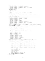
Configure basic MPLS TE, and enable RSVP-TE and CSPF:
# Configure Switch A.
[SwitchA] mpls lsr-id 1.1.1.1
[SwitchA] mpls
[SwitchA-mpls] mpls te
[SwitchA-mpls] mpls rsvp-te
[SwitchA-mpls] mpls te cspf
[SwitchA-mpls] quit
[SwitchA] interface vlan-interface 1
[SwitchA-Vlan-interface1] mpls
[SwitchA-Vlan-interface1] mpls te
[SwitchA-Vlan-interface1] mpls rsvp-te
[SwitchA-Vlan-interface1] quit
# Configure Switch B.
[SwitchB] mpls lsr-id 2.2.2.2
[SwitchB] mpls
[SwitchB-mpls] mpls te
[SwitchB-mpls] mpls rsvp-te
[SwitchB-mpls] mpls te cspf
[SwitchB-mpls] quit
[SwitchB] interface vlan-interface 1
[SwitchB-Vlan-interface1] mpls
[SwitchB-Vlan-interface1] mpls te
[SwitchB-Vlan-interface1] mpls rsvp-te
[SwitchB-Vlan-interface1] quit
[SwitchB] interface vlan-interface 2
[SwitchB-Vlan-interface2] mpls
[SwitchB-Vlan-interface2] mpls te
[SwitchB-Vlan-interface2] mpls rsvp-te
[SwitchB-Vlan-interface2] quit
[SwitchB] interface vlan-interface 4
[SwitchB-Vlan-interface4] mpls
[SwitchB-Vlan-interface4] mpls te
[SwitchB-Vlan-interface4] mpls rsvp-te
[SwitchB-Vlan-interface4] quit
# Follow the same steps to configure Switch C, Switch D, and Switch E.
4.
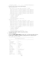
Create an MPLS TE tunnel on Switch A, the headend of the primary LSP:


