188
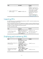
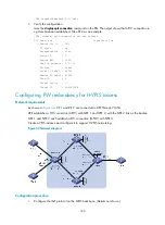
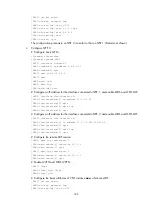
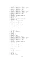
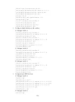
[SwitchC-vsi-vpna-ldp] quit
[SwitchC-vsi-vpna] quit
5.
Verify the configuration:
# Use the
display bfd session verbose
command to display information about the BFD sessions
from Switch A to its neighbors.
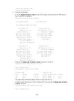
<SwitchA> display bfd session verbose
Total Session Num: 2 Init Mode: Active
Session Working Under Ctrl Mode:
Local Discr: 21 Remote Discr: 20
Source IP: 1.1.1.9 Destination IP: 2.2.2.9
Session State: Up Interface: LoopBack0
Min Trans Inter: 400ms Act Trans Inter: 400ms
Min Recv Inter: 400ms Act Detect Inter: 2000ms
Running Up for: 00:00:01 Auth mode: None
Connect Type: Indirect Board Num: 6
Protocol: MFW/LDP
Diag Info: No Diagnostic
Local Discr: 4 Remote Discr: 0
Source IP: 1.1.1.9 Destination IP: 3.3.3.9
Session State: Up Interface: LoopBack0
Min Trans Inter: 400ms Act Trans Inter: 1000ms
Min Recv Inter: 400ms Act Detect Inter: 3000ms
Running Up for: 00:00:01 Auth mode: None
Connect Type: Indirect Board Num: 6
Protocol: MFW/LDP
Diag Info: No Diagnostic
# Execute the
display vpls connection vsi vpna
command on Switch A.
<SwitchA> display vpls connection vsi vpna
Total 2 connection(s),
connection(s): 1 up, 1 block, 0 down
VSI Name: vpna Signaling: ldp
VsiID VsiType PeerAddr InLabel OutLabel LinkID VCState
100 vlan 2.2.2.9 134312 138882 1 up
100 vlan 3.3.3.9 134216 140476 2 block
The output shows that the link between Switch A and Switch B is up.
# Disconnect the link between Switch A and Switch B. Then, execute the
display vpls connection
vsi vpna
command.
<SwitchA> display vpls connection vsi vpna
Total 1 connection(s),

