225
# Enable LDP globally.
[PE2] mpls ldp
[PE2-mpls-ldp] quit
# Configure PE 2 to establish a remote LDP connection with PE 1.
[PE2] mpls ldp remote-peer 2
[PE2-mpls-ldp-remote-2] remote-ip 192.2.2.2
[PE2-mpls-ldp-remote-2] quit
# Configure the interface connected to the P device and enable LDP on the interface.
[PE2] interface vlan-interface 26
[PE2-Vlan-interface26] ip address 26.2.2.1 24
[PE2-Vlan-interface26] mpls
[PE2-Vlan-interface26] mpls ldp
[PE2-Vlan-interface26] quit
# Configure OSPF.
[PE2] ospf
[PE2-ospf-1] area 0
[PE2-ospf-1-area-0.0.0.0] network 192.3.3.3 0.0.0.0
[PE2-ospf-1-area-0.0.0.0] network 26.2.2.0 0.0.0.255
[PE2-ospf-1-area-0.0.0.0] quit
[PE2-ospf-1] quit
# On the interface connected to CE 2, create a service instance and create a VC.
[PE2] interface gigabitethernet 1/0/1
[PE2-GigabitEthernet1/0/1] port access vlan 10
[PE2-GigabitEthernet1/0/1] service-instance 1000
[PE2-GigabitEthernet1/0/1-srv1000] encapsulation s-vid 10
[PE2-GigabitEthernet1/0/1-srv1000] xconnect peer 192.2.2.2 pw-id 1000
[PE2-GigabitEthernet1/0/1-srv1000] quit
[PE2-GigabitEthernet1/0/1] quit
5.
Configure CE 2:
# Configure an IP address for the interface connected to PE 2.
<Sysname> system-view
[Sysname] sysname CE2
[CE2] interface vlan-interface 10
[CE2-Vlan-interface10] ip address 100.1.1.2 24
6.
Verify your configuration:
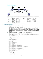
# Display VC information on PE 1. The output shows that a VC has been established.
[PE1] display mpls l2vc
Total ldp vc : 1 1 up 0 down 0 blocked
Transport Client Service VC Local Remote
VC ID Intf ID State VC Label VC Label
1000 GE1/0/1 1000 up 8193 8192
# Display VC information on PE 2. The output shows that a VC has been established.
[PE2] display mpls l2vc
Total ldp vc : 1 1 up 0 down 0 blocked


