193
3.
After PE 2 receives the packet from the public tunnel, it identifies the VC to which the packet
belongs according to the VC label of the packet, deletes the tunnel tag and the VC label from the
packet, and then forwards the resulting packet to CE 2 through the AC bound to the VC.
This packet forwarding process is not applicable to the CCC mode of MPLS L2VPN. For more information
about the CCC mode of MPLS L2VPN, see "
Implementation of MPLS L2VPN
This section describes how to set up a remote MPLS L2VPN connection in different modes.
CCC MPLS L2VPN
The CCC mode sets up a CCC connection by establishing two static LSPs in opposite directions and
binding the static LSPs to ACs.
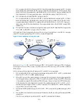
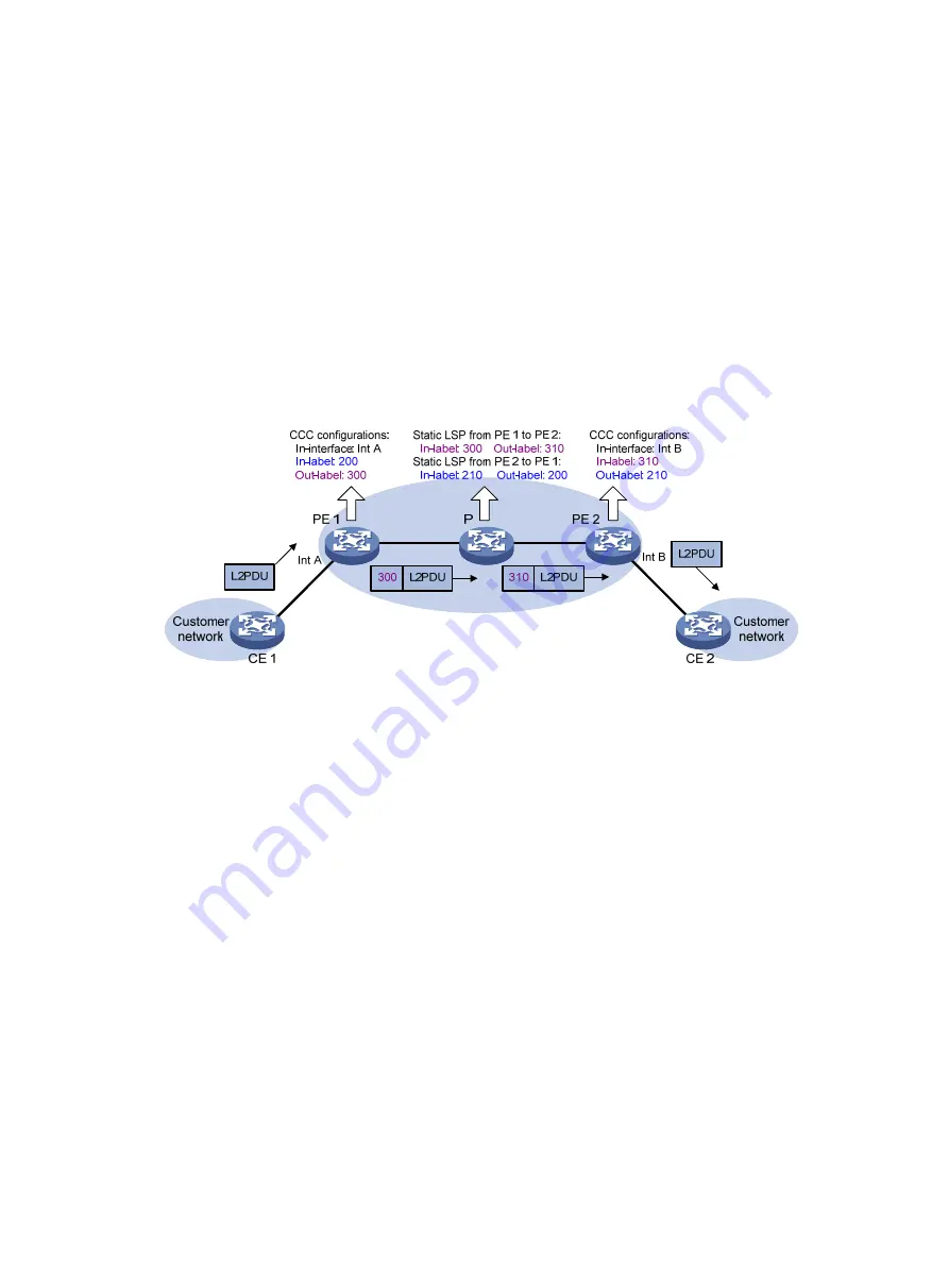
Figure 49
CCC MPLS L2VPN network diagram
After you complete the configurations shown in
, a static LSP from PE 1 to PE 2 and a static LSP
from PE 2 to PE 1 are established. Bind the two LSPs to Interface A on PE 1 and to Interface B on PE 2.
A CCC connection is successfully established.
The following describes how a packet is forwarded from CE 1 to CE 2:
1.
After PE 1 receives a packet from CE 1 on Interface A, it adds label 300 (corresponding to the
static LSP from PE 1 to PE 2) into the packet.
2.
After the P device receives the packet, it looks up the label forwarding table, and swaps label 300
with label 310.
3.
After receiving the packet, PE 2 deletes the label from the packet, and then forwards the packet out
of the bound interface Interface B to CE 2.
Unlike other MPLS L2VPN modes, CCC employs only one level of label to transfer user packets. A static
LSP forwards only packets from the AC bound to the static LSP. Therefore, CCC uses LSPs exclusively. LSPs
used by a CCC connection transfers only CCC connection data. They cannot be used by other
connections or MPLS L3VPN.
SVC MPLS L2VPN
SVC implements MPLS L2VPN by static configuration. It uses two levels of labels to transfer user packets.
The inner labels are statically configured on PEs. No signaling protocol is used.


