3-20
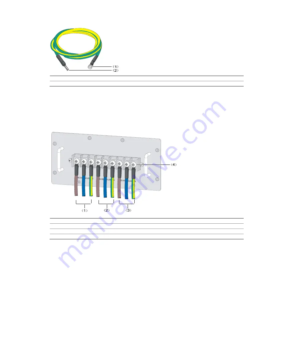
Figure 3-20
PEM-2N power cable
(1) OT terminal (for connecting the PEM-2N)
(2) Crimped connector (for connecting the cabinet busbar)
Follow these steps to connect the PEM-2N power cables:
Step1
Remove the screws from the panel of the PEM-2N, align the OT terminals with the holes of the terminal
blocks, and fasten the screws to fix the OT terminals of the power cables, as shown in Figure 3-21.
Figure 3-21
Connect the power cable to the PEM-2N
(1) Group 1 of 25 A single-phase power cables (for PSUs in Slot 1 and Slot 2)
(2) Group 2 of 25 A single-phase power cables (for PSUs in Slot 3 and Slot 4)
(3) Group 3 of 25 A single-phase power cables (for PSUs in Slot 5 and Slot 6)
(4) Screws for fixing the OT terminals
Step2
Connect the cramped connectors of the power cables to the cabinet busbar, as shown in Figure 3-22.


